VB-C500D - Security Camera CANON - Free user manual and instructions
Find the device manual for free VB-C500D CANON in PDF.

User questions about VB-C500D CANON
0 question about this device. Answer the ones you know or ask your own.
Ask a new question about this device
Download the instructions for your Security Camera in PDF format for free! Find your manual VB-C500D - CANON and take your electronic device back in hand. On this page are published all the documents necessary for the use of your device. VB-C500D by CANON.
USER MANUAL VB-C500D CANON
Thank you for purchasing Canon Network Camera VB-C500VD/VB-C500D (hereafter referred to as VB-C500VD/VB-C500D.)
This Operation Guide describes how to set up and use VB-C500VD/VB-C500D. Read these guides carefully before using VB-C500VD/VB-C500D to ensure that you make the best possible use of this product. Also,
be sure to read the ReadMe file on the Setup CD-ROM.
For the latest information on this product (firmware, bundled software, operation manuals, operating environment, etc.), visit our website.
Copyright
Videos, images or sounds recorded with your VB-C500VD/VB-C500D may not be utilized or published, without consent of copyright holders, if any, except in such a way as permitted for personal use under the relevant copyright law.
Notes
- All rights reserved.
- The contents of this guide are subject to change without any prior notice.
- This document has been prepared with utmost attention to accuracy. If you have any comment, however, please contact the Customer Service Center indicated on the back cover.
- Canon shall assume no liability for any outcome of using this product, regardless of Items 2 and 3 above.
Notes on privacy and publicity rights regarding the utilization of video/audio
When using VB-C500VD/VB-C500D (for video or audio recording), it is the responsibility of the users to take all care to protect privacy and avoid any violation of publicity rights. Canon shall have no liability whatsoever in this regard.
Reference
- Please be sure to gain approval of the building management office before installing a camera, if copyrighted architectural structures or copyrighted premises are got into the frame.
Legal Notice
In some countries or regions, monitoring via a camera is banned by the law or regulation, and the law or regulation depends on the country or region. Before using VB-C500VD/VB-C500D, confirm the law or regulation of the country or region where the camera is used.
Trademark Notice
- Canon and the Canon logo are registered trademarks of Canon Inc.
- Microsoft Windows and Microsoft Internet Explorer are trademarks or registered trademarks of Microsoft Corporation in the United States and other countries.
● Windows is legally recognized as the Microsoft Windows Operating System. - Other brands or product names in this guide are trademarks or registered trademarks of their respective companies.
Notes on Use of Bundled Software VK-Lite (Disclaimer)
Malfunction, failure of VK-Lite or other factors may cause problems, such as recording failure, recorded data corruption or loss. Canon shall have no liability whatsoever for any loss or damages incurred by the user as a result of such problems.
Notes on License Agreement for Bundled Software
See the following files in the BundledSoftware folder inside the LICENSE folder of the bundled Setup CD-ROM for information regarding the license agreement for bundled software.
| Software Type File Name | |
| VB Initial Setting Tool, VBAdmin Tools VBTools.txt | |
| Network Video Recorder VK-Lite VK-Lite.txt |
MPEG-4
NOTICE ABOUT THE MPEG-4 VISUAL STANDARD: THIS PRODUCT IS LICENSED UNDER THE MPEG-4 VISUAL PATENT PORTFOLIO LICENSE FOR THE PERSONAL AND NON-COMMERCIAL USE OF A CONSUMER TO (i) ENCODING VIDEO IN COMPLIANCE WITH THE MPEG-4 VISUAL STANDARD ("MPEG-4 VIDEO") AND/OR (ii) DECODING MPEG-4 VIDEO THAT WAS ENCODED BY A CONSUMER ENGAGED IN A PERSONAL AND NON-COMMERCIAL ACTIVITY. NO LICENSE IS GRANTED OR SHALL BE IMPLIED FOR ANY OTHER USE. ADDITIONAL INFORMATION INCLUDING THAT RELATING TO PROMOTIONAL, INTERNAL AND COMMERCIAL USES AND ADDITIONAL LICENSING MAY BE OBTAINED FROM MPEG LA, LLC. SEE HTTP://WWW.MPEGLA.COM
"This product is licensed under AT&T patents for the MPEG-4 standard and may be used for encoding MPEG-4 compliant video and/or decoding MPEG-4 compliant video that was encoded only (1) for a personal and non-commercial purpose or (2) by a video provider licensed under the AT&T patents to provide MPEG-4 compliant video. No license is granted or implied for any other use for MPEG-4 standard."
Open Source Software
The product (VB-C500VD/VB-C500D and bundled VK-Lite Viewer) contains open source software modules. See OpenSourceSoftware.pdf on the bundled Setup CD-ROM for details. Each module's license conditions are also available in the License folder on the same CD-ROM.
Software under GPL and LGPL
If you would like to obtain the source code under GPL/LGPL, please contact the dealer, where you purchased the product, or a sales agent.
■ Introduction ......ii
How to Read This Document ....viii
Operation Manuals ....viii
Icons Used in This Document ....ix
■ Top Page of the Camera ....x
Accessing the Top Page of the Camera ....x
Accessing the Setting Menu ....xi
Accessing Sample Pages ....xi
Accessing VB-C500 Viewer ....xii
User Authentication when Accessing the Setting Menu or Admin Viewer ....xiii
Chapter 1 Detailed Settings
Setting Menu 1-2
■ Accessing the Setting Menu .... 1-4
Setting Menu .... 1-4
Items Common to All Setting Pages .... 1-5
Setting the Administrator Password, LAN, IPv6, DNS, etc. (Network) 1-7
Setting the Date and Time (Date and Time) 1-12
Setting the Camera Control and External Device Name (Camera) .... 1-14
Setting the Image Size, Quality, Frame Rate,
On-Screen Display of Date and Time, etc. (Video) 1-18
Setting HTTP/FTP Upload and E-mail Notification (Upload) 1-22
Setting the Image Server, Audio Server and HTTP Server (Server) .. 1-28
Setting the Image Buffer, Motion Detection, Audio Playback and Interval Timer (Event) 1-32
■ Setting User Access Privileges (Access Control) 1-37
IPsec Settings (IPsec) 1-41
Setting the Items Requiring Rebooting (Reboot Item) 1-45
Viewing Event Logs and Current Settings, and Performing Maintenance (Maintenance) 1-47
Chapter 2 VBAdmin Tools
Overview of VBAdmin Tools 2-2
VBAdmin Tools 2-2
Motion Detection Setting Tool 2-2
Log Viewer 2-3
Admin Viewer 2-3
■ Launching VBAdmin Tools 2-4
■ Motion Detection Setting Tool 2-7
Log Viewer 2-18
Downloading Log Files 2-18
Viewing Logs 2-19
Chapter 3 VB-C500 Viewer
Overview of VB-C500 Viewer 3-2
Major Differences Between Admin Viewer and VB Viewer 3-2
User Authorities and Camera Control Privileges 3-3
■ Launching VB-C500 Viewer 3-6
Launching VB-C500 Viewer 3-6
Shutting Down VB-C500 Viewer 3-7
Connecting from VBAdmin Tools 3-7
How to Operate VB-C500 Viewer 3-9
Display Screens of Admin Viewer 3-9
Display Screens of VB Viewer 3-11
Obtaining the Camera Control Privilege 3-13
Setting Video and Audio 3-15
Displaying Information 3-18
■ Performing Operations and Settings as the Administrator 3-20
Opening Control for Admin Panel 3-20
Operating the External Device Output 3-21
Displaying the External Device Input Status 3-21
Displaying the Motion Detection Status 3-22
Controlling/Setting the Camera 3-22
Setting the Exposure 3-23
Setting the White Balance 3-25
Setting the Smart Shade Control 3-27
Setting the Night Mode 3-28
Chapter 4 Creating Web Pages for Video Distribution
■ Web Pages for Video Distribution 4-2
■ Viewing Sample Pages 4-4
■ Distributing Video Using VB Viewer 4-6
How to Create a Web Page Using VB Viewer 4-6
Saving Web Page Data 4-6
Example of How to Create a Web Page Using VB Viewer 4-7
VB Viewer Parameters 4-9
■ Distributing Video Using a Browser Only 4-11
Displaying Live Video at the Time of Access as a Still Image 4-11
Example of Image Distribution Using One Global Address 4-12
■ Distributing Still Images to Mobile Phones 4-13
Overwriting a Sample Page 4-14
Chapter 5 Appendix
■ Modifiers 5-2
Troubleshooting 5-4
■ List of Log Messages ....5-7
Log Messages on the VB-C500VD/VB-C500D 5-7
■ List of VB-C500 Viewer Messages 5-17
Messages Displayed in the Information Field 5-17
■ Restore Settings 5-20
Restoring the Settings from the Maintenance Page in the Web Browser .... 5-20
Initializing with the Reset Switch on the Camera 5-21
■ List of Factory Settings 5-23
■ Index 5-31
Operation Manuals
This camera comes with Start Guide, and Operation Guide (this document) included in Setup CD-ROM.
Start Guide (Bundled)
The safety precautions to be followed when using the VB-C500VD/VB-C500D, types of bundled software, operating environment, installation method, initial setting of the camera, etc., are explained. The Start Guide comes with the VB-C500VD/VB-C500D. In this manual, items that should be referenced in the Start Guide are described as follows.
See "Features of VB-C500VD/VB-C500D" (→ Start Guide).
Operation Guide (This Document) (VBC500OG\_E.pdf)
This document explains the basic setting procedures for the VB-C500VD/VB-C500D, how to use VBAdmin Tools and VB-C500 Viewer, troubleshooting, etc. This document is included in the Setup CD-ROM.
Also, a simplified version of the recording software VK-Lite ("Network Video Recorder VK-Lite v.2.2" in Start Guide) is stored in the Setup CD-ROM. The following operation manuals are available:
Setup Guide (VK22SUG\_E.pdf)
This document explains the items to note when using VK-Lite, operating environment, system configuration, installation method and setup method.
Administrator's Manual (VK22AM\_E.pdf)
This document explains details on how to use VK-Lite. Be sure to read this document.
Viewer Operation Guide (VK22VOG\_E.pdf)
This document explains a basic operation of the VK-Lite Viewer. For the detailed operating procedures of the viewer, refer to Administrator's Manual.
Icons Used in This Document
This document uses the following icons to indicate particularly important information the user should read.
| Icon Meaning | |
| Caution | Inappropriate handling against the instruction accompanied by this icon may result in property damage. Be sure to observe these precautions. |
 Note Note | An important item or prohibited item that should always be observed during operation is explained. Be sure to read these instructions to prevent mechanical failure or damage. |
 Tip Tip | Supplementary information or a reference to the operation is explained. Users are recommended to read these memos. |
The top page of the VB-C500VD/VB-C500D showing the setting menu, VB-C500 Viewer display, etc., is explained.
Access the top page of the camera in the web browser.
From the top page of the camera, you can access VB-C500 Viewer for displaying video and the Setting Menu that lets you specify detailed settings of the VB-C500VD/VB-C500D.
If you are accessing the camera for the first time, see the Start Guide bundled with the camera.

Note
This document explains relevant operations based on the IP address 192.168.100.1 (factory setting). In reality, the customer must enter the IP address set for the camera.
Accessing the Top Page of the Camera
- Access http://192.168.100.1/ via the web browser.
- The top page of the camera is displayed.
An overview of each link is given below.

text_image
Network Camera VB-C500 - Windows Internet Explorer https://126.368-100.1/index.html Network Camera VB-C500 VB-C500 Canon ►Deutsch ►English ►Spanish ►Franças ►Italiano ►日本 Setting Page Sample Page VB-C500 Viewer Admin Viewer VB Viewer (1) (2) (3) (4) Done Internet | Protected Mode On 100%(1) Language Button
Use this button to switch the display language.
(2) Setting Page (Setting Menu) Link
Click this link to display the Setting Menu of the camera.
(3) Sample Page Link
Click this link to display sample pages of the camera.
(4) VB-C500 Viewer Launch Link
Clicking this link launches VB-C500 Viewer that displays the video captured with the camera in the web browser.
VB-C500 Viewer consists of two viewers: [Admin Viewer] and [VB Viewer] ( P. 3-2).
● Explanation of each link
[Admin Viewer]
Launches Admin Viewer.
[VB Viewer]
Launches VB Viewer.
Accessing the Setting Menu
To specify detailed settings of the VB-C500VD/VB-C500D, click (2) to proceed to the Setting Menu. For details on the Setting Menu, see "Detailed Settings" in "Chapter 1 Setting Menu" ( P. 1-2).
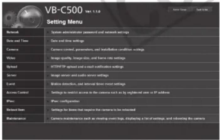
text_image
VB-C500 ver: 1.1.0 Setting Menu Network System administrator password and network settings Date and Time Date and time settings Camera Camera control, parameters, and installation condition settings Video Image quality, image size, and frame rate settings Upload HTTP/FTP upload and e-mail notification settings Server Image server and audio server settings Event Motion detection, and interval timer event settings Access Control Settings to restrict access to the camera such as by registered user or IP address IPsec IPsec configuration Reboot Item Settings for license that require the camera to be rebooted Maintenance Camera maintenance such as viewing event logo, displaying a list of settings, and rebooting the cameraAccessing Sample Pages
To access a sample page, click (3).
One of three sample pages, each showing a still image, video or image for mobile phone, can be displayed.

Tip
For specific ways in which you can utilize the sample pages, see "Chapter 4 Creating Web Pages for Video Distribution" (→ P. 4-2).
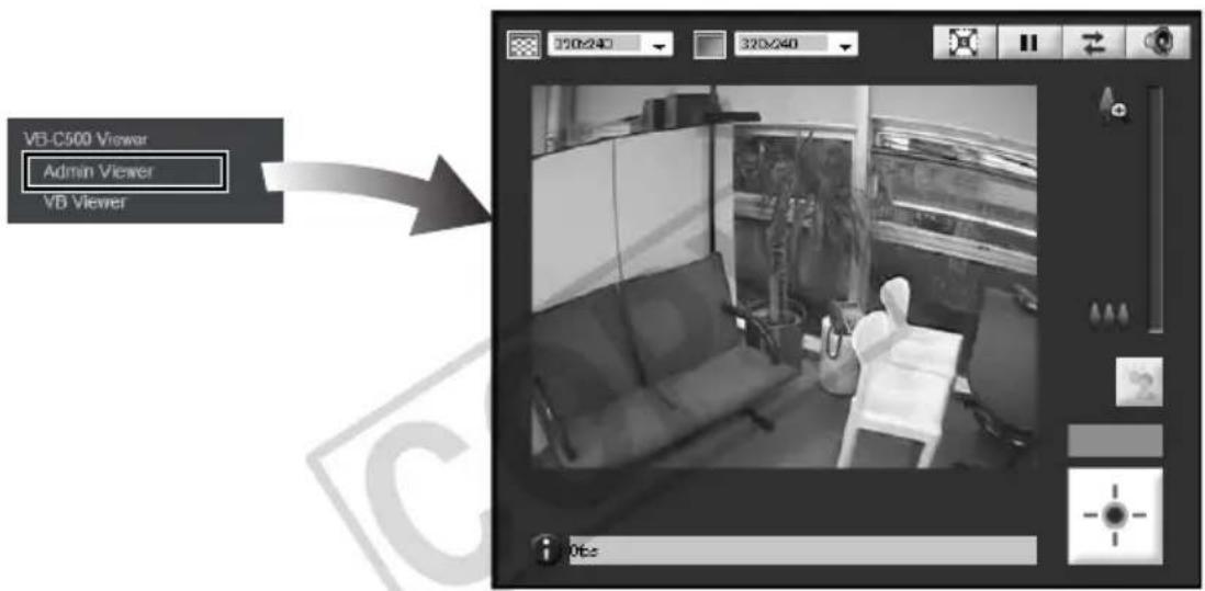
Accessing VB-C500 Viewer
Select [Admin Viewer] or [VB Viewer] from the (4) [VB-C500 Viewer] links to access VB-C500 Viewer.
text_image
VB-C500 Viewer Admin Viewer VB ViewerAdmin Viewer

text_image
VB-C500 Viewer Admin Viewer VB ViewerVB Viewer
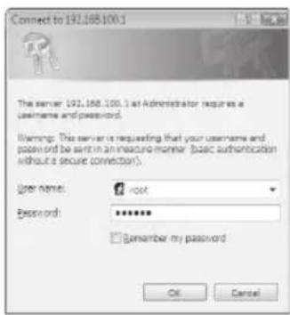
User Authentication when Accessing the Setting Menu or Admin Viewer
User authentication is required when accessing the camera's [Setting Menu] or [Admin Viewer].
text_image
Connect to 192.168.100.1 The server: 192.168.100.1 at Administrator requires a username and password. Warning: This server is requesting that your username and password be sent in an insecure manner (basic authentication without a secure connection). User name: root Password: ******** Remember my password OK CancelAuthentication Screen on [Setting Page]

text_image
Need authentication. User: Password: OK CancelAuthentication Screen on [Admin Viewer]
The factory settings are specified below.
User name: root
Password: camera
The user name "root" is the Administrator account for the camera.
Caution
- Be sure to change the default Administrator password to ensure security of the system. Don't forget the new password.
- If the sample pages ( P. 4-4) must be deleted for security reasons, access the file found at the following path via FTP and back up a copy of the file to a PC, etc., before deleting the sample pages.
Path to English samples : /mnt_flash/www/html/sample/en/
Path to Japanese samples : /mnt_flash/www/html/sample/ja/
Path to Italian samples : /mnt_flash/www/html/sample/it/
Path to German samples : /mnt_flash/www/html/sample/de/
Path to Spanish samples : /mnt_flash/www/html/sample/es/
To restore the deleted sample pages, you must write again to the aforementioned path the copy that had been backed up to a PC, etc. Be sure to create a backup before deleting the samples.

Note
- If the Administrator and authorized user are sharing VB-C500 Viewer on the same PC, it is strongly recommended that the [Remember my password] check box be cleared.
- If a wrong user name or password is entered, the camera cannot be connected. Connect the camera by entering the correct user name and password.
- If you have forgotten the Administrator password, press the reset switch to initialize the settings. See "Initializing with the Reset Switch on the Camera" (→ P. 5-21). Take note, however, that this will reset all settings of the camera, except for time and date, to their factory settings.

Tip
For details on VB-C500 Viewer and user types, see "VB-C500 Viewer" in "Chapter 3 Overview of VB-C500 Viewer" ( P. 3-2).
1
Detailed Settings
The following explains the detailed settings on network connection, camera control, date & time, access control, etc.
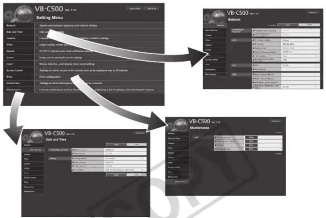
You can move to each setting page from the Setting Menu to set various items regarding the camera.
Items that can be set on each setting page are explained below. See each reference page for details.
- Setting Menu
flowchart
graph TD
    A["VB-C500 Data and Tree"] --> B["Setting Menu"]
    B --> C["Network"]
    C --> D["Data and Tree"]
    D --> E["Camera"]
    E --> F["Video"]
    F --> G["Image quality, image and text"]
    G --> H["Global"]
    H --> I["Image panel and audio server settings"]
    I --> J["Event"]
    J --> K["Before detection, and before timer event settings"]
    K --> L["Access Control"]
    L --> M["Settings for radio access to the camera wall as by registered user or off editions"]
    M --> N["Flow"]
    N --> O["Show configuration"]
    O --> P["Settings for devices that request details to be enabled"]
    P --> Q["Maintenance"]
    Q --> R["Camera maintenance work on information, packaging a bit of settings, and retreating the remote"]

    S["VB-C500 Network"] --> T["Network"]
    T --> U["User Interface"]
    U --> V["User Interface: 1"]
    U --> W["User Interface: 2"]
    U --> X["User Interface: 3"]
    U --> Y["User Interface: 4"]
    U --> Z["User Interface: 5"]

    AA["VB-C500 Maintenance"] --> AB["Network"]
    AB --> AC["Data and Tree"]
    AC --> AD["Camera"]
    AD --> AE["Video"]
    AE --> AF["Image quality, image and text"]
    AF --> AG["Global"]
    AG --> AH["Image panel and audio server settings"]
    AH --> AI["Event"]
    AI --> AJ["Before detection, and before timer event settings"]
    AJ --> AK["Access Control"]
    AK --> AL["Settings for radio access to the camera wall as by registered user or off editions"]
    AL --> AM["Flow"]
    AM --> AN["Show configuration"]
    AN --> AO["Show configuration: 1"]
    AN --> AP["Show configuration: 2"]
    AN --> AQ["Show configuration: 3"]
    AN --> AR["Show configuration: 4"]
- Network
Set the Administrator password, LAN, IPv6, DNS and SNMP ( P. 1-7).
- Date and Time
Set the date & time and time zone of the camera ( P. 1-12).
- Camera
Set the camera name, startup settings, camera control, day/night, installation conditions, external input device name and external output device name ( P. 1-14).
- Video
Set the image quality, image size and frame rates in JPEG and MPEG-4, and on-screen display settings of date and time and other information ( P. 1-18).
- Upload
Set HTTP/FTP upload and e-mail notification ( P. 1-22).
- Server
Set the image server, audio server and HTTP server ( P. 1-28).
Event
Set the image buffer, motion detection, external device input, interval timer and audio file upload ( P. 1-32).
- Access Control
Set the authorized user accounts, user privileges and host access restriction ( P. 1-37).
IPsec
Set IPsec ( P. 1-41).
- Reboot Items
"Setting the Items Requiring Rebooting (Reboot Item)" (→ P. 1-45)
- Maintenance
"Tool" (View Log Events, View Current Settings, Reboot, Restore Settings) (→ P. 1-47).

Note
Notes on Use with Windows Vista/XP
- When the [Windows Security Alert] dialog box appears, click the [Unblock] button. Once this button is clicked, this warning dialog box will no longer appear.
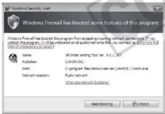
text_image
Windows Firewall has blocked some features of this program Name: VB Initial Setting Tool Ver. 5.0.1.107 Publisher: CANON DIC. Path: C:\program files\canon\webview\joint\5.1\joint.exe Network locations: Public network What are network locations! Keep blocking Unlock- If the dialog box appears and pop-up is blocked when accessing [HELP] of each setting page or [View Log Events] or [View Current Settings] on the maintenance page, enable [Pop-up] by following the procedure explained in the information bar.
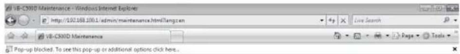
text_image
VB-CX30D Maintenance - Windows Internet Explorer http://102.168.100.1/admin/maintenance.html/Tang.cen Live Search VB-CX30D Maintenance Page Tools Pop-up blocked. To see this pop-up or additional options click here.The various settings of the VB-C500VD/VB-C500D are specified by accessing the camera in the web browser. First, access the top page ( P. x).
For entry of the user name and password, see "User Authentication when Accessing the Setting Menu or Admin Viewer" (→ P. xiii).
Setting Menu
You can access each setting page and Admin Viewer from the Setting Menu.
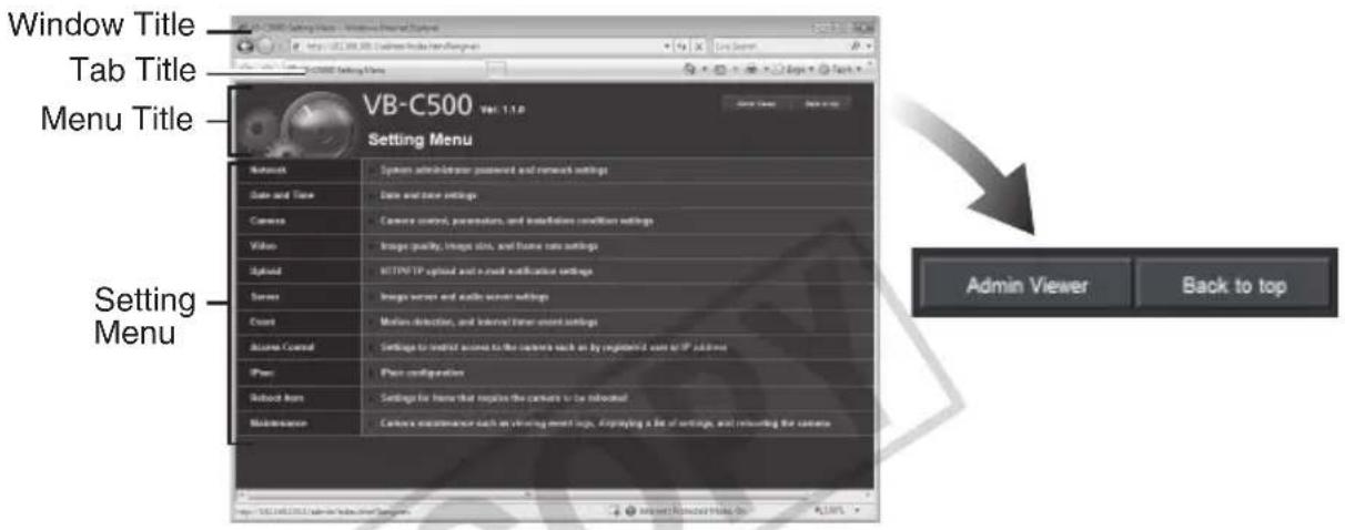
text_image
Window Title Tab Title Menu Title VB-C500 Vol. 1.1.0 Setting Menu Network System administrator password and network settings Data and Time Data and time settings Camera Camera control, parameters, and installation conditions settings Video Image quality, image size, and frame rate settings USB/FTP upload and email notification settings Server Image server and audio server settings Count Motion detection, and Internet timer event settings Active Control Settings to limit access to the camera back on by registered user or IP users Phone Plan configuration Desktop Item Settings for home that requires the camera to be returned Maintenance Camera maintenance each on viewing event info. Applying a file of settings, and returning the camera.(1) Window Title
Displays the model name of the connected camera.
(2) Tab Title
Displays the model name of the connected camera.
(3) Menu Title
The camera's model name is displayed as "VB-C500."
(4) [Back to top] button
Clicking this button switches the display to the top page of the camera.
(5) [Admin Viewer] Button
Clicking this button switches the display to Admin Viewer.
(6) Setting Menu
Clicking a desired button switches the display to each setting page.

Note
Once all settings are complete on the setting page, close the browser for security reasons.
Items Common to All Setting Pages
■ Application of Setting Changes
When any setting is changed on each setting page, the grayed-out [Apply] button shown on the top right of the setting page turns blue.

text_image
Apply ClearTo make the new setting effective, click the [Apply] button.
To restore the original setting, click the [Clear] button.
■ Setting Changes Requiring Rebooting
The items whose setting will become effective only after the camera is rebooted are accompanied by an orange icon.

text_image
IP Address Setting ManualIf any item accompanied by an orange icon is changed, the [Apply] button shown on the top right of each setting page changes to [Apply and reboot].

text_image
■ Reboot Apply and reboot ClearTo confirm the new setting, click the [Apply and reboot] button. The new setting will be reflected and the camera will be rebooted.
To restore the original setting, click the [Clear] button.
Note
Changed details are lost if you move to another setting page without first clicking the [Apply] button or the [Apply and reboot] button. To validate changed settings, be sure to click either the [Apply] button or the [Apply and reboot] button.
■ Returning to the Setting Menu
To return to the Setting Menu from each setting page, click the [Settings menu] button on the top right of the setting page.
VB-C500
Ver. 1.1.0


Note
- Be sure to change the settings of each camera within one setting page.
- Do not move between setting pages using the [Back] and [Forward] buttons of the browser. The new settings may return to the original settings or unwanted setting changes may occur.

Tip
Clicking ① [Help] to the left of each item on the setting page displays a detailed explanation of each setting item.
Network
■: Reboot
Apply
Clear
You can set the following items.
- Administrator Password
Set the Administrator password.
• LAN
Set the IP address and other items needed to establish LAN connection.
IPv6
Set IPv6.
• DNS
Set the name server address, host name and DDNS.
SNMP
Set the SNMP.
Administrator Password

text_image
Administrator Password Password Up to 8 characters Confirm Password Up to 8 characters(1) [Password]
Set the Administrator password. You can use up to eight (single-byte) ASCII characters (space or printable characters). The factory setting is "camera." If Admin Viewer or VBAdmin Tools is connected, disconnect the applicable item before changing the password.
(2) [Confirm Password]
Enter the same password for confirmation.
![CANON VB-C500D - [Confirm Password] - 1](/content/2026/06/1214332/images/d591a6b10631bc7fe44f16b846fa14870347ad3f2543ab85db328ddd57f5fe8e.jpg)
Note
- Be sure to change the default Administrator password to ensure security of the system. Don't forget the new password.
- If you have forgotten the Administrator password, press the reset switch to initialize the settings. See "Initializing with the Reset Switch on the Camera" (→ P. 5-21). Take note, however, that this will reset all settings of the camera, except for time and date, to their factory settings.
LAN
| LAN | IP Address Setting | Manual |
| IP Address | 192.168.100.1 | |
| Subnet Mask | 255.255.255.0 | |
| Default Gateway Address | ||
| LAN Interface | Auto | |
| Maximum Packet Size 578:1500 | 1500 |
(1) [IP Address Setting]
Select [Auto (DHCP)] or [Manual] as the address setting mode. If [Auto (DHCP)] is selected, the values automatically acquired from the DHCP server will be entered in [IP Address], [Subnet Mask] and [Default Gateway Address]. If [Manual] is selected, directly enter the values appropriate for the environment in which the camera is used.
(2) [IP Address]
If [Manual] was selected in (1), enter a fixed IP address.
(3) [Subnet Mask]
If [Manual] was selected in (1), enter the subnet mask specified for each network.
(4) [Default Gateway Address]
Enter an appropriate value if [Manual] was selected in (1). Be sure to set the default gateway address when connecting the camera to a subnet different from that of the viewer.
(5) [LAN Interface]
Select [Auto], [Full Duplex] or [Half Duplex]. Normally [Auto] should be used.
(6) [Maximum Packet Size]
Enter the maximum transmission unit. Normally the default setting of 1500 needs not be changed.
![CANON VB-C500D - [Maximum Packet Size] - 1](/content/2026/06/1214332/images/4424b53d4d936e560076d414c54e35067ec07b3fae2cfecc5c28924cc60f88eb.jpg)
Note
- For [IP Address], [Subnet Mask] and [Default Gateway Address], contact your network administrator.
- If any of the [IP Address], [Subnet Mask] and [Default Gateway Address] settings is wrong, network access may be disabled. In this case, use VB Initial Setting Tool Ver. 5.0.1 to set the address again. See "Perform Initial Setting of the Camera" (→ Start Guide).
- If the [IP Address], [Subnet Mask], [Default Gateway Address], [LAN Interface] or [Maximum Packet Size] setting is changed, the camera may become no longer accessible from the active browser. Check beforehand the precautions explained in "Notes" in "Setting the Items Requiring Rebooting (Reboot Item)" (→ P. 1-46). Also check the precautions in the same section before changing each setting in "IPv6" (→ P. 1-9) and "DNS" (→ P. 1-10).
- If [Auto (DHCP)] is selected as the address setting mode, the IP address may not be assigned correctly in certain environments, such as when a router is present between the DHCP server and this camera. In this case, assign a fixed IP address by selecting [Manual].
- If you are using IPv6, set 1280 or greater value under [Maximum Packet Size].

Tip
- If optical fiber or ADSL is used, slightly decreasing the maximum packet size may increase the sending efficiency.
- The IP address assigned by [Auto (DHCP)] can be checked using the VB Initial Setting Tool.
IPv6
| IPv6 | IPv6 | Enable |
| IPv6 Address |
(1) [IPv6]
Select [Disable] or [Enable] regarding the use of IPv6.
(2) [IPv6 Address]
If [Enable] is selected for IPv6, an automatically acquired address will be shown.
![CANON VB-C500D - [IPv6 Address] - 1](/content/2026/06/1214332/images/dd025b34e95a6b9693fdebd1fe3d665c7a180e52481a77d186fb8ad5ca8419f7.jpg)
Tip
In an environment where IPv6 cannot be used, the [IPv6 Address] field remains blank even when [Used] is selected for IPv6.
DNS
| DNS | Name Server Address 1 | |
| Name Server Address 2 | ||
| Host Name Up to 63 characters | ||
| Host Name Registration with DDNS | Disable |
(1) [Name Server Address 1], [Name Server Address 2]
Enter each name server address you want to register. If only one address is registered, keep the [Name Server Address 2] field blank.
(2) [Host Name Registration with DDNS]
Select [Enable] and enter the host name. The host name can be registered in the name server.
You can use up to 63 (single-byte) characters including A to Z, a to z, 0 to 9, "-" (hyphen), "-" (underber) and "." (period).

Tip
- For added convenience, register the host name if the camera is use by [Auto (DHCP)] ( P. 1-8). Certain items must be set beforehand for registration in the DNS server. For the DNS server settings, contact your System Administrator.
- If [Name Server Address 1] cannot be used, [Name Server Address 2] will be accessed. However, [Name Server Address 2] must be already set.
SNMP
| SNMP | SNMP | Enable |
| Community Name Up to 31 characters | public | |
| Administrator Contact InformationUp to 63 characters | ||
| Administration Function NameUp to 31 characters | ||
| Installation LocationUp to 31 characters |
(1) [SNMP]
Select whether to use SNMP from [Disable] or [Enable]. When [Enable] is selected, the SNMP Manager can reference information set in the camera.
(2) [Community Name]
Set a community name for SNMP. It is recommended that you change the default community name to ensure security of the system.
(3) [Administrator Contact Information]
Set contact information (e-mail address, etc.) for the Administrator of the camera. The set details can be referenced by the SNMP Manager.
(4) [Administration Function Name]
Set the camera name used for administration. The set name can be referenced by the SNMP Manager.
If this field is left blank, "VB-C500VD" is used by default when the connected camera is VB-C500VD, and "VB-C500D" when the connected camera is VB-C500D.
(5) [Installation Location]
Set information regarding the installation location of this camera. The set name can be referenced by the SNMP Manager.
![CANON VB-C500D - [Installation Location] - 1](/content/2026/06/1214332/images/036c8ada1829e0ef56e749c87102a8ee2cb08931927947f1ed24a9cf6bb34699.jpg)
Tip
● The information set in the camera is read-only from the SNMP Manager.
- Use the SNMP Manager SNMP MIB2 (supporting RFC1213).
● The camera's SNMP does not support IPv6.
Date and Time
Apply
Clear
You can set the following items.
● Current Date and Time
The date and time set in the camera is shown.
- Setting
Select the date & time setting method and time zone for this camera.
Current Date and Time
| Current Date and Time | Date yyyy/mm/dd | 2008/05/23 |
| Time hh:mm:ss | 09:43:57 |
[Date], [Time]
The date and time currently set in the camera is shown.
Setting
| Setting | Setting Method | Set manually |
| Date yyyy/mm/dd | 2008/05/23 | |
| Time hh:mm:ss | 09:43:67 | |
| Time Zone | (GMT+09:00) Osaka, Sapporo, Tokyo |
(1) [Setting Method]
Select [Set manually], [Synchronize with NTP server], [Synchronize with NTP broadcast] or [Synchronize with computer time].
(2) [Date], [Time]
Set the following items according to the selection for [Setting Method] made in (1).
[Set manually]
You can set a desired date and time. Enter the date in the order of
Example: To specify August 23, 2008 1:23:04 pm, enter "2008/08/23" and "13:23:04."
| Setting | Setting Method | Set manually |
| Date yyyy/mm/dd | 2008/05/23 | |
| Time hh:mm:ss | 09:43:57 | |
| Time Zone | (GMT+09.00) Osaka, Sapporo, Tokyo |
[Synchronize with NTP server]
The camera will synchronize with that time of the NTP server. Enter the IP address of the NTP server.
| Setting Method | Synchronize with NTP server |
| NTP Server (IP Address) | |
| Time Zone | (GMT+09-00) Osaka, Sapporo, Tokyo |
[Synchronize with NTP broadcast]
The camera will synchronize with the NTP broadcast time.
| Setting Method | Synchronize with NTP broadcast |
| Time Zone | (GMT+09 00) Osaka, Sapporo, Tokyo |
[Synchronize with computer time]
The camera will synchronize with the date and time of the computer currently accessing the camera. The time zone will also be selected automatically.
| Setting Method | Synchronize with computer time |
| Date yyyy/mm/dd | 2008/05/31 |
| Time hours | 20:35:39 |
| Time Zone | (GMT+09:00) Osaka, Sapporo, Tokyo |
(3) [Time Zone]
Select from the list an applicable time difference from the Greenwich Mean Time.

Tip
- If [Synchronize with computer time] is selected, clicking the [Apply] button to apply the setting will cause the setting shown under [Setting Method] to change to [Set manually].
- If [Synchronize with NTP Server] is selected, the date and time will not be changed when the IP address of the NTP server is wrong or otherwise the NTP server cannot be connected.
● The camera's NTP does not support IPv6.
Camera
■ : Reboot
Apply
Clear
You can set the following items.
- Camera Name
Enter the name of the camera. The camera name is required if VK-64, etc., is used with the camera. - Initial Camera Settings
Set the AF Mode, Slow Shutter and Shutter Speed. - Camera Control
Set the digital zoom.
Day/Night
Set the Day/Night switching mode.
● Installation Conditions
Set the image flip.
● External Device Name
Set the external input device name and external output device name.
Camera Name
Camera Name

Camera Name (alphanumeric characters) Up to 15 characters
Camera
[Camera Name]
Be sure to enter the camera name using up to 15 ASCII characters (space or printable characters).
![CANON VB-C500D - [Camera Name] - 1](/content/2026/06/1214332/images/0c7e139de1fe3d14581a28846f7fa9c413c17a322556baa1b966dacbab250c8d.jpg)
Tip
If you are using an optional recording software (VK-64/VK-16 or bundled VK-Lite), the camera name set here will be shown when the camera is registered.
Initial Camera Settings
| Initial Camera Settings | AE Mode | Auto |
| Slow Shutter | Disable | |
| Initial Camera Settings | AE Mode | Shutter-priority AE |
| Shutter Speed | 1/100 |
| Initial Camera Settings | AE Mode | Shutter-priority AE |
| Shutter Speed | 1/100 |
[AE Mode], [Slow Shutter], [Shutter Speed]
Set the camera exposure control and shutter speed.
[AE Mode]
[Auto]
The exposure is controlled automatically.
[Flickerless]
In this mode, image flickers caused by fluorescent lights, etc., can be reduced. The shutter speed is automatically adjusted according to the brightness of the environment in which the camera is used.
[Shutter-priority AE]
In this mode, a desired shutter speed can be specified.
[Slow Shutter]
Slow shutter can be set only when [Auto] is selected under [AE Mode].
Set the maximum slow shutter time to be used in the auto exposure mode when capturing video in a dark place. Select [Disable], [1/15] or [1/8]. The longer the shutter time, the more likely a residual image generates when a moving subject is captured. Accordingly, select an appropriate time according to the capture condition.
[Shutter Speed]
Shutter Speed can be set only when [Shutter-priority AE] is selected under [AE Mode]. Select a desired shutter speed of the camera from the 12 levels from [1/8] to [1/8000]. When capturing a moving subject, selecting a higher shutter speed lets you capture less blurry image.

Note
- If the subject is a traffic signal, electronic scoreboard, etc., the captured image may flicker. In this case, try changing the [AE Mode] setting to [Shutter-priority AE] and selecting a shutter speed lower than 1/100, to see if the problem improves.
- The Initial Camera Settings items define the defaults that apply when the camera is started. Setting changes will be reflected only after the camera is reconnected or camera is rebooted. Specify the settings used in the actual operating environment, using "Control for Admin" in VB-C500 Viewer (→ P. 3-20).
Camera Control

text_image
Camera Control Digital Zoom Disable[Digital Zoom]
Select [Enable] or [Disable] for digital zoom.
* The higher the digital zoom ratio, the lower the image quality becomes.
Day/Night
| Day/Night | Mode | Auto |
| Switching Brightness | Standard | |
| Response (sec.) | 20 |
(1) [Mode]
Select [Manual] or [Auto] as the Day/Night mode.
If [Manual] is selected, you can manually switch [Day Mode] and [Night Mode] using the Admin Viewer Night Mode function ( P. 3-28).
If [Auto] is selected, set [Switching Brightness] and [Response (sec.)] according to the environment in which the camera is installed as well as the desired switching condition.
(2) [Switching Brightness]
Set the brightness at which the Day mode and Night mode will be switched. Select [Darker], [Slightly Darker], [Standard], [Slightly Brighter] or [Brighter]. Select [Darker] to capture video in color whenever possible.
Select [Brighter] to reduce noise. Note that this will cause the camera to switch to black & white earlier.
(3) [Response (sec.)]
Set the time in seconds needed to make judgment on day/night mode switching. Select [5], [10], [20], [30] or [60].
If the brightness remains above or below the level set in (2) for the number of seconds set above, the day mode and night mode will switch.
Select [30] or [60] if the brightness changes frequently due to passing of a light source in front of the camera, etc. Select [5] or [10] if the brightness does not change much.
![CANON VB-C500D - [Response (sec.)] - 1](/content/2026/06/1214332/images/684e31eeb6cc6b74a271823946d0659efe6894bff6faaa35c5e2a533cdafeacb.jpg)
Note
- If you want to set [Auto] for [Day/Night], conduct a thorough operation test and check the effectiveness of the setting beforehand.
- If [Auto] is selected under [Day/Night], set [Auto], [Auto (Flickerless)], or [Auto (Shutter-priority AE)] under [Exposure] on VB-C500 Viewer (→ P. 3-23).
- If [Night Mode] is selected, image does not become brighter even when infrared lamp is used.
- If [Auto] is selected under [Day/Night], zoom does not work while switching between [Day Mode] and [Night Mode].
Installation Conditions

text_image
Installation Conditions Image Flip Disable[Image Flip]
Select whether or not to output image after rotating it by 180^ . Set [Enable] or [Disable] according to the installation conditions of the camera. The factory setting is [Disable].
External Input Device 1, 2/External Output Device 1, 2
| External Input Device 1 | Device Name (alphanumeric characters) Up to 15 characters | |
| External Input Device 2 | Device Name (alphanumeric characters) Up to 16 characters |
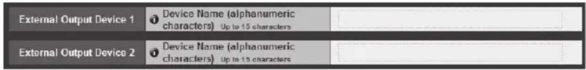
text_image
External Output Device 1 Device Name (alphanumeric characters) Up to 15 characters External Output Device 2 Device Name (alphanumeric characters) Up to 15 characters[External Input Device]/[External Output Device]
Be sure to enter each device name to identify the corresponding external device being connected. Enter the device name (single-byte alphanumeric) using up to 15 characters (ASCII characters (space or printable characters) excluding a double quotation mark (")).
![CANON VB-C500D - [External Input Device]/[External Output Device] - 1](/content/2026/06/1214332/images/32dcf61d370922c78ec3acf3e999e1f899a777f7331f087e8ba13170da2dcae9.jpg)
Tip
If you are using Admin Viewer or optional recording software (VK-64/VK-16 or bundled VK-Lite), the external device name set here will be displayed.

text_image
Video ■ : Reboot Apply ClearYou can set the following items.
- JPEG
Set the image quality, size and maximum frame rate in JPEG.
MPEG-4
Set the video quality, size and capture frame rate in MPEG-4. - On-screen display
Set the on-screen display of date and time or text strings on the image.
JPEG
| JPEG | Image Quality: 160 x 120 | 3 |
| Image Quality: 320 x 240 | 3 | |
| Image Quality: 640 x 480 | 3 | |
| Image Size: Image Transmission | 320 x 240 | |
| Maximum Frame Rate: Image Transmission 0.1-30 | 30.0 | |
| Image Size: Upload | 320 x 240 |
(1) [Image Quality]
Select a desired quality from 1 to 5 (total 5 levels) for image transmitted at each image size in JPEG.
The greater the value, the higher the quality becomes.
(2) [Image Size: Image Transmission]
Select the image size used when transmitting images from [160 × 120] , [320 × 240] or [640 × 480] . The default image size used by each viewer is selected.
(3) [Maximum Frame Rate: Image Transmission]
Limit the maximum transmission frame rate per second to reduce the viewer load. The maximum is 30 frames/sec. Enter a desired value from 0.1 up to 30.0.
(4) [Image Size: Upload]
Select [160 x 120], [320 x 240] or [640 x 480] for the image size of transmitted image using the upload function. For details of upload settings, see "Setting HTTP/FTP Upload and E-mail Notification (Upload)" (→ P. 1-22).
MPEG-4
| MPEG.4 | Video Quality | 3 |
| Video Size | 320 x 240 | |
| Capture Frame Rate | 30 |
(1) [Video Quality]
Select a desired quality from 1 to 5 (total 5 levels) for video transmitted in MPEG-4. The greater the value, the higher the quality becomes.
(2) [Video size]
Select [320 x 240] or [640 x 480] for the size of video transmitted.
(3) [Capture Frame Rate]
Select [10], [15] or [30] (fps) as the capture frame rate.
![CANON VB-C500D - [Capture Frame Rate] - 1](/content/2026/06/1214332/images/464d1097556037ab23249869caa009e212147990f3e8c6f3067b5d8742bd7202.jpg)
Note
- If a higher video size or quality is set, the data size per frame will increase and the network load will increase.
JPEG : The frame rate may drop.
MPEG-4 : Video may be temporarily disrupted.
- The data size may increase depending on the type or movement of the subject. If the frame rate remains low or other undesirable condition continues for a long period, lower the image size or quality setting.
● Take note that if you are using the optional recording software VK-64/VK-16 or bundled VK-Lite, the hard disk utilization will also be affected during recording.
On-Screen Display
| On-screen display | Date display | Enable |
| Position of date display | Upper left | |
| Format of date display | YYYY/MM/DD | |
| Time display | Enable | |
| Position of time display | Upper left | |
| Text display | Display designated string | |
| Position of text display | Upper left | |
| Text string displayUp to 15 characters | A value is not specified. | |
| Color of text | Black | |
| Color of text outline | White | |
| Color depth of text and outline | Fill text and outline |
(1) [Date display]
Select whether or not to display the date on the image. Date information is superimposed on the image when [Enable] is selected.
(2) [Position of date display]
Select the position to display date information from [Upper left], [Upper right], [Lower left], or [Lower right].
(3) [Format of date display]
Select the date display format from [YYYY/MM/DD], [DD/MM/YYYY], or [MM/DD/YYYY].
(4) [Time display]
Select whether or not to display the time on the image. Time information is superimposed on the image when [Enable] is selected.
(5) [Position of time display]
Select the position to display time information from [Upper left], [Upper right], [Lower left], or [Lower right].
(6) [Text display]
Select an option for displaying a text string superimposed on the image from [Display nothing], [Display designated string], or [Display camera name].
When [Display designated string] is selected, the string set under (8) [Text string display] is displayed.
When [Display camera name] is selected, the string set under [Camera Name (alphanumeric characters)] on the [Camera] menu ( P. 1-14) is displayed.
(7) [Position of text display]
Select the position to display the text string from [Upper left], [Upper right], [Lower left], or [Lower right].
(8) [Text string display]
Set a text string of 15 alphanumeric characters or less to superimpose on the image when (6) [Text display] is set to [Display designated string].
(9) [Color of text]
Select the color of the text to be superimposed on the image from [Black], [Blue], [Cyan], [Green], [Yellow], [Red], [Magenta], or [White].
(10)[Color of text outline]
Select the text outline color from [Black], [Blue], [Cyan], [Green], [Yellow], [Red], [Magenta], or [White].
(11)[Color depth of text and outline]
Select the color depth of the text and outline to superimpose on the image from [Fill text and outline], [Make text only transparent], [Make text only translucent], or [Make text and outline translucent].
![CANON VB-C500D - (11)[Color depth of text and outline] - 1](/content/2026/06/1214332/images/a6324d1be059968046c070675628eb6d3a083117aca5e898bc7f2d148a425630.jpg)
Note
The time superimposed with the on-screen display is not suitable for uses that require high reliability. If high reliability is always required for monitoring, etc., use this information as reference only.

Tip
- The date and time superimposed with the on-screen display may not match the date and time set in [Current Date and Time] (→ P. 1-12).
- Depending on image quality settings, the on-screen display may be difficult to read. Perform settings with checking the actual image.
- Motion detection detects on-screen display text (→ P. 2-11). Adjustments should be made as necessary.
text_image
Upload ■ : Reboot OK ClearYou can set the following items.
- General Upload
Set the upload operations. - HTTP Upload
Set the upload via HTTP connection.
- FTP Upload
Set the upload via FTP connection.
E-mail Notification
Set items relating to sending of event information and video by e-mail.
General Upload

text_image
General Upload Upload HTTP Upload[Upload]
Select [Upload Disabled], [HTTP Upload] or [FTP Upload] as the upload mode.
![CANON VB-C500D - [Upload] - 1](/content/2026/06/1214332/images/484704c9eb23beed27d659542c6526e08c1501560d5c627cec2c10187dd6436d.jpg)
Note
- If the upload function is used, the [Event] menu must also be set (→ P. 1-32).
- If you are using both e-mail notification by text and video and image upload by HTTP/FTP, set [320 x 240] or less under [Image Size: Upload] (→ P. 1-18)
- If the camera is set to perform upload or e-mail notification continuously, not all video or e-mail may be sent according to the image size and network condition until the server. In this case, an event log message is displayed.

Tip
To lower the upload or e-mail notification load, try the following measures. Also check the settings including network to the server.
- Reduce the image file size:
- Set a lower value under [Image Quality] for JPEG ( P. 1-18).
- Set a lower value for [Image Size: Upload] for JPEG ( P. 1-18).
- Reduce the uploading frequency:
- Reduce the value in [Pre-event Buffer (number of image frames)] or [Post-event Buffer (number of image frames)] (→ P. 1-32).
- If [Motion Detection Event] is enabled, disable [ON Event Operation], [OFF Event Operation] or [Continuous Motion Operation] (→ P. 1-33).
- If [External Device Input Event] is enabled, disable [ON Event Operation or [OFF Event Operation] (→ P. 1-34).
- If [Interval Timer Event] is enabled, increase the value in [Interval of the Timer] (→ P. 1-36).
- Reduce the e-mail notification frequency:
- If [Motion Detection Event] is enabled, disable [ON Event Operation], [OFF Event Operation] or [Continuous Motion Operation] (→ P. 1-33).
- If [External Device Input Event] is enabled, disable [ON Event Operation or [OFF Event Operation] (→ P. 1-34).
- If [Interval Timer Event] is enabled, increase the value in [Interval of the Timer] ( P. 1-36).
HTTP Upload
| HTTP Upload | # Notification | Notification Only with HTTP | |
| # URI Up to 255 characters | |||
| # User Name Up to 31 characters | |||
| # Password Up to 31 characters | ********** | ||
| # Proxy Server Up to 63 characters | |||
| # Proxy Port 1 - 65535 | 80 | ||
| # Proxy User Name Up to 31 characters | |||
| # Proxy Password Up to 31 characters | ********** | ||
| # Parameter (query string) Up to 127 characters | |||
| # HTTP Upload Test | Exec | ||
(1) [Notification]
Select [Notification Only with HTTP] or [Image attached Notification with HTTP] as the content of notification.
(2) [URI]
Enter the URI to upload to (using up to 255 characters).
(3) [User Name], [Password]
Enter the user name and password required for authentication.
(4) [Proxy Server]
Enter the host name or IP address of the proxy server (using up to 63 characters).
(5) [Proxy Port]
Enter the port number of the proxy server (default = [80]).
(6) [Proxy User Name], [Proxy Password]
Enter the user name and password of the proxy server.
(7) [Parameter (query string)]
Enter an appropriate parameter (using up to 127 characters). The parameter can be entered using "%" characters ( P. 5-2).
(8) [HTTP Upload Test]
Clicking the [Exec] button initiates an upload test based on the settings currently applied.

Note
Enter [Proxy Server], [Proxy Port], [Proxy User Name] and [Proxy Password] if connecting via a proxy.
FTP Upload
| FTP Upload | # Notification | Image data upload with FTP |
| # FTP Server Up to 63 characters | The value is not specified. | |
| # User Name Up to 31 characters | The value is not specified. | |
| # Password Up to 63 characters | ||
| # PASV Mode | Disable | |
| # File Upload Path Up to 265 characters | ||
| # File Naming | YYMMDDHHMMSSms | |
| # FTP Upload Test | Exec |
(1) [Notification]
The content of content is set to [Image data upload with FTP].
(2) [FTP Server]
Enter the host name or IP address of the FTP server (using up to 63 characters).
(3) [User Name], [Password]
Enter the user name and password required for authentication.
(4) [PASV Mode]
Select [Enable] or [Disable] for the PASV mode when uploading via FTP.
(5) [File Upload Path]
Enter the path to the folder to upload the image file to (using up to 255 characters).
(6) [File Naming]
Set a desired file naming mode.
[YYMMDDHHMMSSms]
Image is uploaded according to the file name format of
"{year}{month}{day}{hour}{minute}{second}{ms}.jpg." Example: 20080123112122000.jpg)
[YYMMDD Directory/HHMMSSms]
A subdirectory named "{year}{month}{day}" is created first, and then the image is uploaded using the file name "{hour}{minute}{second}{ms}.jpg."
(Example: 20080123/112122000.jpg)
[Loop]
Image is updated under a file name consisting of a number up to the value set in
[Maximum Number of Loops]. (Example: 0000.jpg, 0001.jpg)
[User Setting]
Image is updated under the file name specified by [Subdirectory Name to Create] and [File Name to Create].
| File Naming | Loop |
| Maximum Number of Loops0 - 9999 | 0 |
[Maximum Number of Loops]
If [Loop] is selected as the recording mode, enter the maximum number of loops in a range of 0 to 9999.
| File Naming | User Setting | |
| Subdirectory Name to CreateUp to 127 characters | ||
| File Name to CreateUp to 127 characters | image jpg | |
| FTP Upload Test | Exoc | |
[Subdirectory Name to Create], [File Name to Create]
If File Naming is set to [User Setting], enter the subdirectory name to be created as well as the name of the created file (using up to 127 characters).
Each parameter can be entered using "%" characters (→ P. 5-2).
(7) [FTP Upload Test]
Clicking the [Exec] button initiates an upload test based on the settings currently applied.
E-mail Notification
| E-mail Notification | Notification | Text Only | |
| Mail Server NameUp to 63 characters | |||
| Mail Server Port 1-65536 | 25 | ||
| Sender (From) Up to 63 characters | |||
| Recipient (To) Up to 63 characters | |||
| Authentication | None | ||
| Subject Up to 31 characters | |||
| Message Body Up to 255 characters | |||
| E-mail Notification Test | Exec | ||
(1) [Notification]
Select [Text only] or [Text with image] as the content of notification.
(2) [Mail Server Name]
Enter the host name or IP address of the SMTP server (using up to 63 characters).
(3) [Mail Server Port]
Enter the port number of the SMTP server (default = [25]).
(4) [Sender (From)]
Set the e-mail address of the sender (using up to 63 characters).
(5) [Recipient (To)]
Set the e-mail address of the recipient (using up to 63 characters).
(6) [Authentication]
Select [None], [POP before SMTP] or [SMTP-AUTH] as the e-mail authentication mode.
Set an appropriate mode according to the authentication mode used by the SMTP server to send to.
[User Name], [Password], [POP Server]
If [POP before SMTP] is selected as the e-mail authentication mode, enter the user name, password, and host name or IP address of the POP server, required for authentication.
| Authentication | POP before SMTP |
| User Name Up to 31 characters | username |
| Password Up to 31 characters | ***** |
| POP Server Up to 63 characters | servername |
[User Name], [Password]
If [SMTP-AUTH] is selected as the e-mail authentication method, enter the user name and password required for authentication.
| Authentication | SMTP-AUTH |
| User Name Up to 31 characters | username |
| Password Up to 31 characters | ***** |
(7) [Subject]
Enter the subject of the e-mail to be sent (using up to 31 characters).
(8) [Message Body]
Enter the message (text) of the e-mail to be sent (using up to 255 characters). The test can be entered by parameters having "%" characters (→ P. 5-2).
(9) [E-mail Notification Test]
Clicking the [Exec] button initiates an e-mail notification test based on the settings currently applied.
Server
■ : Reboot
Apply
Clear
You can set the following items.
- Image Server
Set the items needed to deliver image from the camera. - Audio Server
Set the items relating to transmitting/receiving audio. - HTTP Server
Set the HTTP port and web page delivery.
Image Server
| Image Server | Maximum Number of Clients 0 - 30 | 30 |
| Camera Control Queue Length0 - 30 | 30 | |
| Maximum Connection Time (sec.)0 - 60030 | 0 | |
| Camera Control Time (sec.)1 - 3500 | 20 |
(1) [Maximum Number of Clients]
Set the maximum number of clients that can be connected to the camera at the same time. Up to 30 clients can be set. If 0 is set, connection is prohibited except for Admin Viewer.
(2) [Camera Control Queue Length]
Set the maximum queue length of requests for the camera control privilege from clients. The maximum number is 30. Enter an integer from 0 to 30. If 0 is set, camera control is prohibited except by the Administrator.
(3) [Maximum Connection Time (sec.)]
Set the time in seconds during which an individual client can connect to the camera. The maximum time is 65535 seconds. Enter an integer from 0 to 65535.
If 0 is entered, the connection time becomes unlimited.
(4) [Camera Control Time (sec.)]
Set the maximum time during which the viewer can control the camera. The maximum time is 3,600 seconds. Enter an integer from 1 to 3600.
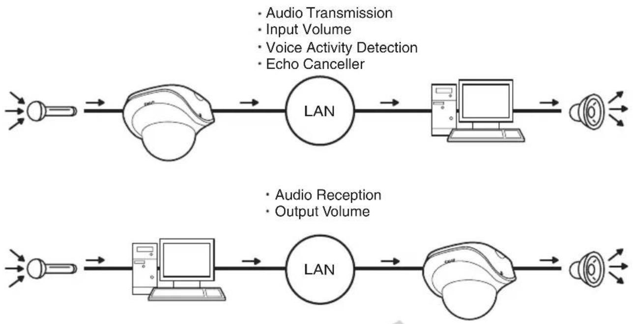
Audio Server
| Audio Server | Audio Transmission from the Camera | Enable |
| Input Volume 1-100 | 50 | |
| Voice Activity Detection | Enable | |
| Audio Reception from Viewer | Enable | |
| Output Volume 1-100 | 50 | |
| Echo Canceller | Enable | |
| Audio Input | Line In |
(1) [Audio Transmission from the Camera]
When [Enable] is selected, the audio input through the microphone attached to the camera can be transmitted to VB-C500 Viewer.
(2) [Input Volume]
Set the volume of input sound in a range of 1 to 100. The greater the value, the larger the input volume becomes.
(3) [Voice Activity Detection]
If [Enable] is selected, the audio transmission size is reduced temporarily when no audio is output. This way, the load of the applicable network can be reduced.
(4) [Audio Reception from Viewer]
If [Enable] is selected, the audio from the optional VK Viewer or bundled VK-Lite Viewer can be received and output from the speaker with amplifier connected to the camera.
(5) [Output Volume]
Set the volume of output sound in a range of 1 to 100. The greater the value, the larger the output volume becomes.
(6) [Echo Canceller]
If [Enable] is selected, echo between the microphone and speaker is suppressed.
(7) [Audio Input]
Set the microphone input. Select [Line In], [Microphone In (dynamic microphone)] or [Microphone In (condenser microphone)].
flowchart
graph LR
    A["Input Light"] --> B["Central LAN"]
    B --> C["Computer"]
    C --> D["Speaker"]
    E["Audio Transmission"] --> B
    F["Input Volume"] --> B
    G["Voice Activity Detection"] --> B
    H["Echo Canceller"] --> B
    I["Audio Reception"] --> J["Computer"]
    K["Output Volume"] --> J
    L["Input Light"] --> M["Central LAN"]
    M --> N["Computer"]
    N --> O["Speaker"]
    P["Audio Reception"] --> Q["Computer"]
    R["Output Volume"] --> Q
Caution
Switch [Line In] and [Microphone In] on each setting page according to the specification of the microphone ( P. 1-29).
If a wrong input is used, the camera or microphone may be damaged. Be sure to set the correct input.

Note
- The volume, sound quality, etc., may change depending on the characteristics of the microphone used.
- To output audio from the audio output terminal of the camera, send audio from VK Viewer. Audio cannot be sent from VB-C500 Viewer. See "VK-Lite Viewer Audio Transmission/ Reception (Two-way Communication)" (→ Start Guide).
- Connect a speaker with amplifier to the camera. See "Audio Input/Output Terminals" (→ Start Guide).
- If [Enable] is selected under [Echo Canceller], the sound quality or volume may be affected. Utilize this function as necessary according to the installation environment and how the camera is used.
- When sending audio, read "Notes" in "Audio Input/Output Terminals" of Start Guide carefully.
HTTP Server
| HTTP Server | HTTP Port 80,1024 - 65535 | 80 |
| Global Address for the Web Page | IP Address | |
| IP Address (global address for the web page) | ||
| Port Number (global address for the web page) 1 - 65535 |
(1) [HTTP Port]
Set the HTTP port number in a range of 80 and 1024 to 65535.
Normally 80 should be used.
(2) [Global Address for the Web Page]
If a fixed global address is assigned to the camera using the NAT function of the router ( P. 4-12), set the global address and port number here. If [IP Address] is selected, enter the specified IP address in the [IP Address] field. If [Host Name] is selected, the host name specified in [DNS] under [Network] will be used. Set the necessary items under [DNS] ( P. 1-10).
![CANON VB-C500D - [Global Address for the Web Page] - 1](/content/2026/06/1214332/images/84ace3ae6843315675b556626c24b1aa3917a149dc7605d520a5c1b35f412e9b.jpg)
Note
- If the setting of [HTTP port] is changed, the camera may no longer become accessible from the active browser. Check beforehand the precautions explained in "Notes" in "Setting the Items Requiring Rebooting (Reboot Item)" (→ P. 1-46).
- If [IP Address] is selected under [Global Address for the Web Page], be sure to set both [IP Address (global address for the web page)] and [Port Number (global address for the web page)]. If [Host Name] is selected, also be sure to set [Host Name] under [DNS] on the [Network] setting page.
Event
Apply
Clear
You can set the following items.
- Image Buffer
Set the items associated with the temporary saving of image in the image buffer. - Motion Detection
Set the operation to be performed at the time of motion detection. - External Device Input
Set the operation to be performed when an event is input from an external device. - Interval Timer
Set the timer period for e-mail notification or upload. - Sound Clip Upload
Set the audio file to be registered as a sound playback.
Image Buffer
| Image Buffer | Frame Rate 1 - 10 | 1 |
| Pre-event Buffer (number of image frames) 0 - 100 | 0 | |
| Post-event Buffer (number of image frames) 0 - 100 | 0 |
(1) [Frame Rate]
Set the frame rate that applies when image is temporarily saved in the image buffer when an event occurs.
(2) [Pre-event Buffer (number of image frames)]
Set the number of images to be buffered before the event.
(3) [Post-event Buffer (number of image frames)]
Set the number of images to be buffered after the event.

Note
● The maximum image buffer size is approx. 4 MB.
If a high image size is set, the Frame Rate, Pre-event Buffer and Post-event Buffer may not be achieved as specified ( P. 1-22).
- If buffering cannot be achieved as specified, an event log message appears.
Before using such high image size, confirm that no messages are shown in the event log ( P. 1-22).
Motion Detection
| Motion Detection | # Motion Detection Event | Enabled |
| # ON Event Operation | Enable ▼ | |
| # OFF Event Operation | Enable ▼ | |
| # Continuous Motion Operation | Enable ▼ | |
| # Upload | Enable ▼ | |
| # E-mail Notification | Enable ▼ | |
| # Audio Playback at ON Event | Enable ▼ | |
| # Audio Playback at OFF Event | Enable ▼ | |
| # Sound Clip | sound1 ▼ | |
| # Volume 1 - 100 | 50 |
(1) [Motion Detection Event]
Whether motion detection events are enabled/disabled is shown. The value of this item can be changed using Motion Detection Setting Tool in VBAdmin Tools ( P. 2-7). When motion detection events are enabled, event notification to the viewer is performed according to the displayed motion detection event of this camera such as Admin Viewer.
(2) [ON Event Operation]
Select the operation to be performed upon an ON event. If [Enable] is selected, (5), "Upload" and (6), "E-mail Notification" are displayed. When the mode changes to [Detected] (ON event), the process set in (5) or (6) is performed.
(3) [OFF Event Operation]
Select the operation to be performed upon an OFF event. If [Enable] is selected, (5), "Upload" and (6), "E-mail Notification" are displayed. When the [Detected] mode is finished (OFF event), the process set in (5) or (6) is performed.
(4) [Continuous Motion Operation]
Select the operation to be performed during motion detection. If [Enable] is selected, (5), "Upload" and (6), "E-mail Notification" are displayed. When the mode changes to [Detected] (detected period), the process set in (5) or (6) is performed.
(5) [Upload]
Select the upload operation. If [Enable] is selected, upload is performed every time a motion detection event occurs. To use this function, the [General Upload] sub-menu and [HTTP Upload] or [FTP Upload] sub-menu must also be set from the [Upload] menu.
(6) [E-mail Notification]
Select the e-mail notification operation to be performed. If [Enable] is selected, e-mail notification is performed every time a motion detection event occurs. To use this function, the [E-mail Notification] sub-menu must also be set from the [Upload] menu.
(7) [Audio Playback at ON Event]
Select the audio playback operation to be performed upon an ON event. If [Enable] is selected, the sound specified under [Sound Clip] will be played when the mode changes to [Detected] (ON event).
(8) [Audio Playback at OFF Event]
Select the audio playback operation to be performed upon an OFF event. If [Enable] is selected, the sound specified under [Sound Clip] will be played when the mode changes to [Detected] (OFF event).
(9) [Sound Clip]
Select the audio to be played. For registration of sound clip, see "Sound Clip Upload" ( P. 1-36).
(10) [Volume]
Select the volume of sound clip using an integer of 1 to 100. The greater the value, the larger the volume becomes.
![CANON VB-C500D - [Volume] - 1](/content/2026/06/1214332/images/60134e83f5e28a3991c3a9c08d5b21e37e32d8ed2f6044fd4fe475f45c5d56e3.jpg)
Note
- The motion detection function cannot be interlocked with external device output. However, interlocking is possible if the optional recording software VK-64/VK-16 is used.
- For precautions on motion detection, see "Notes on Use of Motion Detection, Streaming and Bundled Recording Software VK-Lite" (→ Start Guide).
External Device Input
| External Device Input | External Device Input Event | Enable |
| External Device Input 1 | ON Event Operation | Enable |
| OFF Event Operation | Enable | |
| Upload | Enable | |
| E-mail Notification | Enable | |
| Audio Playback at ON Event | Enable | |
| Audio Playback at OFF Event | Enable | |
| Sound Clip | sound2 | |
| Volume 1-100 | 50 |
(1) [External Device Input Event]
Select whether to [Enable] or [Disable] external device input events.
(2) [ON Event Operation]
Select the operation to be performed upon an ON event. If [Enable] is selected, (4), "Upload," (5) and "E-mail Notification" are displayed. When an ON input is received from an external device (ON event), the processes set in (4) and (5) are performed.
(3) [OFF Event Operation]
Select the operation to be performed upon an OFF event. If [Enable] is selected, (4), "Upload," (5) and "E-mail Notification" are displayed. When the input from an external device turns OFF (OFF event), the processes set in (4) and (5) are performed.
(4) [Upload]
Select the upload operation. If [Enable] is selected, upload is performed when an event is input from an external device. To use this function, the [General Upload] sub-menu and [HTTP Upload] or [FTP Upload] sub-menu must also be set from the [Upload] menu.
(5) [E-mail Notification]
Select the e-mail notification operation to be performed. If [Enable] is selected, e-mail notification is performed when an event is input from an external device, provided that [Enable] is selected. To use this function, the [E-mail Notification] sub-menu must also be set from the [Upload] menu.
(6) [Audio Playback at ON Event]
Select the audio playback operation to be performed upon an ON event. If [Enable] is selected, the sound specified in [Sound Clip] is played when an ON event is input from an external device.
(7) [Audio Playback at OFF Event]
Select the audio playback operation to be performed upon an OFF event. If [Enable] is selected, the sound specified in [Sound Clip] is played when the event input from an external device turns OFF.
(8) [Sound Clip]
Select the audio to be played. For registration of sound clip, see "Sound Clip Upload" ( P. 1-36).
(9) [Volume]
Select the volume of sound clip using an integer of 1 to 100. The greater the value, the larger the volume becomes.
Interval Timer
| Interval Timer | Interval Timer Event | Enable |
| Interval of the Timer | 1 min. | |
| Upload | Disable | |
| E-mail Notification | Disable |
(1) [Interval Timer Event]
Select whether to [Enable] or [Disable] timer events. If [Enable] is selected, (2), "Timer Interval," (3), "Upload" and (4), "E-mail Notification" are displayed.
(2) [Interval of the Timer]
Select a desired timer interval from the pull-down menu in a range of [1 sec.] to [24 hours].
(3) [Upload]
Select the upload operation. If [Enable] is selected, upload is performed at the specified intervals. To use this function, the [Upload] menu must also be set.
(4) [E-mail Notification]
Select the e-mail notification operation to be performed. If [Enable] is selected, e-mail notification is performed at the specified intervals. To use this function, the [E-mail Notification] sub-menu must also be set from the [Upload] menu.
Sound Clip Upload
| Sound Clip Upload 1 | Browse File | Browse... | Add |
| Sound Clip NameUp to 15 characters | Delete |
(1) [Browse File]
Specify the audio file to be registered as a sound playback, and then click [Add].
(2) [Sound Clip Name]
Set the name of the audio file to be registered as a sound playback (using up to 15 characters). To delete a registered sound, click [Delete] next to the name of the playback sound you want to delete.
![CANON VB-C500D - [Sound Clip Name] - 1](/content/2026/06/1214332/images/a309312f7bf801705c19576188108f3b82e3e2d4b0053abe0263ea6bba46cf90.jpg)
Tip
Only audio files of the ".wav" file format whose play time is no longer than 20 seconds ( -law, PCM 8 bits, sampling frequency 8000 Hz, monaural) can be set.

text_image
Access Control OK ClearYou can set the following items.
- Authorized User Account
Register users who can access this camera. - User Authority
Set the privileges of authorized users and guest users. - Host Access Control
Specify the hosts from which access is permit and restricted.
Authorized User Account

text_image
Authorized User Account User Name Up to 8 characters Password Up to 8 characters Add User List Delete(1) [User Name], [Password]
Enter the user name and password and then click [Add]. The authorized user will be added to the user list.
The user name can consist of up to eight (single-byte) characters of A to Z, a to z, 0 to 9, "-" (hyphen) and "-" (underber).
The password can consist of up to eight (single-byte) ASCII characters (space or printable characters).
(2) [User List]
A list of authorized users is shown. User privileges can be set for these users. Up to 50 users can be registered other than the Administrator (root).
Also, the user list can be sorted using the ▲ and ▼ buttons on the right.
To delete a user, select the applicable user from the user list and then click [Delete].
User Authority
| User Authority | Privileged Camera Control | Camera Control | Image Distribution | Audio Distributionc | |
| ① Authorized User | ✓ | ✓ | ✓ | ||
| Guest User | ✓ | ✓ |
[Privileged Camera Control], [Camera Control], [Image Distribution], [Audio Distribution]
Set the user privileges of authorized users and guest users. Select the check boxes corresponding to the items you want to permit for each user.

Tip
Authorized users can have higher privileges than guest users.
Host Access Restriction
| Host Access Restriction | Host List Up to 30 items | |
| Apply the list to HTTP Server | No | |
| Apply the list to Image Transmission | No | |
| Apply the list to Audio Transmission | No |
(1) [Host List]
A list of hosts from which access is permitted and restricted is shown.
(2) [Apply the list to HTTP Server]
If [Yes] is selected, the host list is applied to HTTP server access. Not only access from various viewers, but access to the top page and setting pages is also limited.
The list is also applied when distributing image and audio.
(3) [Apply the list to Image Transmission]
If [Yes] is selected, the host list is applied when the image distribution function is used. Access from various viewers can be restricted.
The list is also applied when distributing audio.
(4) [Apply the list to Audio Transmission]
If [Yes] is selected, the host list is applied when the audio distribution function is used. Utilization of audio can be restricted.

Note
- If no host list is available, access is permitted to all hosts.
- If a host list is given that indicates prohibition of all accesses, the host restriction function is disabled and access is permitted to all hosts.
- To prohibit access via a proxy server in HTTP connection, a proxy server address must be set.
- If Host Access Restriction is set wrongly, access to the setting pages itself may be prohibited, in which case restoring the factory settings will become the only means for recovery.
- If host access control is implemented, this camera cannot be accessed by IPv6.
- If the [Host List] or [Apply the list to HTTP Server] setting is changed, the camera may become no longer accessible from the active browser. Check beforehand the precautions explained in "Notes" in "Setting the Items Requiring Rebooting (Reboot Item)" (→ P. 1-46).

Tip
The Host Access Restriction function restricts the hosts on which the viewer and other client applications are running, where access is restricted using a list containing one or more entries in the following format.
Listing Format
[!] addr [-addr2]
- "addr" conforms to the standard IP address format.
- "addr" and "addr2" give a range of IP addresses, and if IP address A is addr or larger but addr2 or smaller, A is included in the range of addr to addr2. addr2 can be omitted, in which case value of addr2 becomes the same as that of addr.
- If the entry starts with "!, " access is prohibited. If "!" does not precede the entry, access is permitted.
- If a given host address corresponds to multiple entries, whether access is permitted or prohibited is determined by the setting of the first applicable entry after the beginning of the host list. Accordingly, take note that in Examples 3 to 5 below, an entry of permitted address must be specified in an entry of prohibited address.
- Redundant and conflicting entries in the list are automatically deleted from the list.
- If the host address does not belong to any entry, access is permitted.
Example of description
Example 1. Prohibit access from a given access
!172.20.0.10
Access from the host whose address is 172.20.0.10 is prohibited.
Example 2. Prohibit access from hosts in a given range
!172.20.0.0-172.20.0.20
Access from the hosts whose address is in a range of 172.20.0.0 to 172.20.0.20 is prohibited.
Example 3. Permit access from hosts in a given range and prohibit access from all other hosts
172.20.0.10-172.20.0.12
!0.0.0.0-255.255.255.0
Access is permitted only from the hosts whose address is in a range of 172.20.0.10 to 172.20.0.12.
Example 4. Prohibit access from hosts in a given range, but permit access from hosts at certain addresses within that range
172.20.0.10
!172.20.0.0-172.20.0.20
Access from the hosts whose address is in a range of 172.20.0.0 to 172.20.0.20 is prohibited, but access is permitted only from the host whose address is 172.20.0.10.
Example 5. Prohibit access from hosts in a given range, but permit access from hosts in a given range within that range
172.20.0.10-172.20.0.15
!172.20.0.0-172.20.0.20
Access from the hosts whose address is in a range of 172.20.0.0 to 172.20.0.20 is prohibited, but access is permitted from the hosts whose address is in a range of 172.20.0.10 to 172.20.0.15.
text_image
IPsec ■ : Reboot Apply ClearYou can set the following items.
● Various settings can be specified for up to five communicating devices.
IPsec Set
IPsec Sets 1 to 5 are available, where IPsec settings for each communication using each IPsec Set.
| IPsec Set 1 | IPsec | Manual |
| IPsec Mode | Tunnel Mode | |
| Destination Address (IPv4/IPv6) | 192.168.200.0 | |
| Source Address (IPv4/IPv6) | 192.168.100.1 | |
| Security Protocol | ESP | |
| Security Gateway Address (IPv4/IPv6) | 192.168.10.1 | |
| Destination Prefix Length | 24 |
(1) [IPsec]
Select [Manual] if IPsec will be used. Select [Disable] if IPsec will not be used.
(2) [IPsec Mode]
Select [Tunnel Mode] or [Transport Mode] as the IPsec operation mode.
(3) [Destination Address (IPv4/IPv6)]
Enter the IP address of the connection destination.
(4) [Source Address (IPv4/IPv6)]
Enter the IP address of the sender.
(5) [Security Protocol]
Select [ESP], [AH] or [ESP and AH] as the IPsec protocol to be used.
If [ESP] is selected, enter only the setting items relating to ESP.
If [AH] is selected, enter only the setting items relating to AH.
If [ESP and AH] is selected, enter all setting items.
(6) [Security Gateway Address (IPv4/IPv6)]
If the IPsec operation mode was set to [Tunnel Mode] in (2), set the IP address of the security gateway.
(7) [Destination Prefix Length]
This setting is required only when the IPsec operation mode was set to [Tunnel Mode] in (2).
Enter a desired prefix length for connection destination in a range of 0 to 128.
If IPv4 is used, enter a desired length in a range of 0 to 32.
■ If [ESP] or [ESP and AH] was set under [Security Protocol] in (5), the following items must be set.
| IPsec | Manual |
| IPsec Mode | Tunnel Mode |
| Destination Address(IPv4/IPv6) | 192.168.200.0 |
| Source Address (IPv4/IPv6) | 192.168.100.1 |
| Security Protocol | ESP |
| Security Gateway Address(IPv4/IPv6) | 192.168.10.1 |
| Destination Prefix Length | 24 |
| SA ESP Encryption Algorithm | AES |
| SA ESP Authentication Algorithm | HMAC_SHA1_96 |
| SA ESP Encryption Key(outbound) | 0F445981962E9AC7E79385E037C35FC3 |
| SA ESP Authentication Key(outbound) | BB64787768DFC8DE7EB4D84EC81B453168F3B32F |
| SA ESP SPI (outbound) | 1000 |
| SA ESP Encryption Key(inbound) | 6F822A37272BF55EB581A91A53770C57 |
| SA ESP Authentication Key(inbound) | 81E4DC85387FB09192B26CA1A2FBD97202159B96 |
| SA ESP SPI (inbound) | 2000 |
(8) [SA ESP Encryption Algorithm]
Select [AES], [3DES], [DES] or [NULL] as the ESP encryption algorithm according to the encryption algorithm supported by the device to connect to.
Normally [AES] or [3DES] is recommended.
(9) [SA ESP Authentication Algorithm]
Select [HMAC_SHA1_96], [HMAC_MD5_96] or [No Authentication] as the ESP authentication algorithm according to the authentication algorithm supported by the device to connect to.
If [ESP] is used alone, [No Authentication] cannot be selected.
(10) [SA ESP Encryption key (outbound)]
Set the SA encryption key for outbound. If [AES], [3DES] or [DES] was selected in (8), set a 128-bit, 192-bit or 64-bit hexadecimal, respectively. [This item need not be set if [NULL] was selected.
(11) [SA ESP Authentication key (outbound)]
Set the SA authentication key for outbound. If [HMAC_SHA1_96] or [HMAC_MD5_96] was set in (9), set a 160-bit or 128-bit hexadecimal, respectively. This item need not be set if [No Authentication] was selected.
(12) [SA ESP SPI (outbound)]
Set the SA SPI value for outbound. Set a desired value in a range of 256 to 4294967295.
(13) [SA ESP Encryption key (inbound)]
Set the SA encryption key for inbound. If [AES], [3DES] or [DES] was selected in (8), set a 128-bit, 192-bit or 64-bit hexadecimal, respectively. This item need not be set if [NULL] was selected.
(14) [SA ESP Authentication key (inbound)]
Set the SA authentication key for inbound. If [HMAC_SHA1_96] or [HMAC_MD5_96] was set in (9), set a 160-bit or 128-bit hexadecimal, respectively. This item need not be set if [No Authentication] was selected.
(15) [SA ESP SPI (inbound)]
Set the SA SPI value for inbound. Set a desired value in a range of 256 to 4294967295. Since this setting is used as an ID for identifying the SA, be careful not to specify an inbound SPI whose value is already used the SPI for other ESP.
■ If [AH] or [ESP and AH] was set under [Security Protocol] in (5), the following items must be set.
| Security Protocol | AH |
| Security Gateway Address(IPv4/IPv6) | 192.168.10.1 |
| Destination Prefix Length | 24 |
| SA AH Authentication Algorithm | HMAC_SHA1_96 |
| SA AH Authentication Key(outbound) | 6F92282D51B290EA4B51D8833A4EFF295A6E5F40 |
| SA AH SPI (outbound) | 3000 |
| SA AH Authentication Key(inbound) | 7E0E6F639A0A81A83B6C5642EFE859881B2883AE |
| SA AH SPI (inbound) | 4000 |
(16) [SA AH Authentication Algorithm]
Select [HMAC_SHA1_96] or [HMAC_MD5_96] as the AH authentication algorithm according to the authentication algorithm supported by the device to connect to.
(17) [SA AH Authentication key (outbound)]
Set the SA authentication key for outbound. If [HMAC_SHA1_96] or [HMAC_MD5_96] was set in (16), set a 160-bit or 128-bit hexadecimal, respectively.
(18) [SA AH SPI (outbound)]
Set the SA SPI value for outbound. Set a desired value in a range of 256 to 4294967295.
(19) [SA AH Authentication key (inbound)]
Set the SA authentication key for inbound. If [HMAC_SHA1_96] or [HMAC_MD5_96] was set in (16), set a 160-bit or 128-bit hexadecimal, respectively.
(20) [SA AH SPI (inbound)]
Set the SA SPI value for inbound. Set a desired value in a range of 256 to 4294967295. Since this setting is used as an ID for identifying the SA, be careful not to specify an inbound SPI whose value is already used the SPI for other AH.
![CANON VB-C500D - [SA AH SPI (inbound)] - 1](/content/2026/06/1214332/images/6fa79bade026b8b3d7c190e712747353a4cb68ed025a19e1fca09d1454f389fd.jpg)
Note
- To use this camera using IPsec, the communicating destinations and network must be set beforehand. For these settings, contact your System Administrator.
- If any setting is changed from the [IPsec] menu, the camera may no longer become accessible from the active browser. Check beforehand the precautions explained in "Notes" in "Setting the Items Requiring Rebooting (Reboot Item)" (→ P. 1-46).

text_image
Reboot Item ■ : Reboot Apply ClearThe following items that require rebooting, if changed, are gathered here.
● LAN, IPv6, Installation Conditions, MPEG-4, HTTP Server
| LAN | IP Address Setting | Manual |
| IP Address | 192.168.100.1 | |
| Subnet Mask | 256.255.255.0 | |
| Default Gateway Address | ||
| LAN Interface | Auto | |
| Maximum Packet Size 576-1500 | 1500 | |
| IPv6 | IPv6 | Enable |
| Installation Conditions | Image Flip | Disable |
| MPEG-4 | Video Size | 320 x 240 |
| Capture Frame Rate | 30 | |
| HTTP Server | HTTP Port 80,1024-65535 | 80 |
(1) [LAN]
IP address and other settings required for LAN Connection ( P. 1-8)
(2) [IPv6]
Settings relating to use of IPv6 ( P. 1-9)
(3) [Installation Conditions]
Settings relating to camera installation conditions ( P. 1-17)
(4) [MPEG-4]
Settings relating to image size and frame rate in MPEG-4 ( P. 1-19)
(5) [HTTP Server]
HTTP port number settings ( P. 1-31)

Note
These settings relate to network connection. If any setting is changed to a value that may disable camera connection from the active browser, the following dialog box is displayed to alert the user.

text_image
Windows Internet Explorer There are some changes which may cause disconnection from the browser. Continue? OK CancelTo apply the new setting, click [OK].
Depending on the new setting, it may not be possible to connect to the camera again after rebooting. In this case, a candidate URI is displayed as shown below, if available, to facilitate reconnection to the camera.
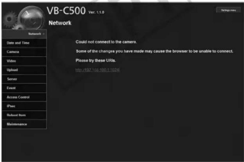
text_image
VB-C500 Ver. 1.1.0 Network Could not connect to the camera. Some of the changes you have made may cause the browser to be unable to connect. Please try these URIs. http://92.108.100.1:1024If you want to connect to the camera again, try using the displayed URI. If the camera cannot be connected using the displayed URI, contact your System Administrator.
* In the [Reboot Item] menu, the [IP Address Setting], [IP Address], [Subnet Mask], [Default Gateway Address], and [HTTP Port] settings relate to network connection.
Viewing Event Logs and Current Settings, and Performing Maintenance (Maintenance)
Maintenance
■:Reboot
The following items can be used here.
- Tool
Display and initialize the settings of the camera.
Tool
| Tool | ✓ View Log Events | View | |
| ✓ View Current Settings | View | ||
| ✓ Reboot | Exec | ||
| ✓ Restore Settings | Exec |
(1) [View Log Events]
Historical data of the camera such as operations and connections with various viewers, etc., is shown.
(2) [View Current Settings]
A list of current settings is shown.
(3) [Reboot]
The camera is rebooted.
All setting items of this camera, except for the Administrator password, network settings (IP address setting, IP address, subnet mask, default gateway), date and time, time zone, LAN interface, maximum transmission unit and use of IPv6, are reset to their factory settings and values set by the user discarded. Clicking this button reboots the camera automatically.
Note
While [Restore Settings] is in progress, never turn off the camera. If the power is turned off, the camera may not reboot correctly.

Tip
- It is recommended that you write down the current settings before restoring the factory settings using [Restore Settings] (→ P. 5-20).
- Although the camera can also be reset to the initial state using the reset switch, take note that the reset switch initializes all settings (→ P. 5-21).
COPY
2
VBAdmin Tools
How to set the camera using VBAdmin Tools is explained. You can set the motion detection, view logs, and start Admin Viewer. Set each item after specifying the necessary detailed settings according to Chapter 1.
VBAdmin Tools consists of multiple applications for [Motion Detection Setting Tool], [Log Viewer] and [Admin Viewer]. You can remotely set the camera, view privileged images, check the operating condition, acquire logs, and perform other operations with ease.
VBAdmin Tools (→P.2-4)
This is the main panel for VBAdmin Tools. You can start each tool from this panel. First, install VBAdmin Tools. See "Install the Necessary Software" (→ Start Guide).

text_image
VBAadmin Tools File Help Host name 152.168.100.1 Setting tools Motion Detection Setting Tool Viewers Log Viewer Admin Viewer ExitMotion Detection Setting Tool ( P. 2-7)
This tool is used to set the motion detection function that performs upload, notifies the viewer, records a log, etc., if a change has occurred in the captured image due to movement of a subject. You can set the position and size of the motion detection area, detection judgment conditions, etc., while checking the image on the camera.
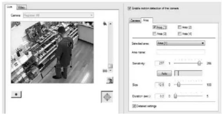
text_image
Video Camera: Engineer 81 Grainle motion detection of the camera Camera Area Area (1) Area (2) Area (3) Area (4) Selected area: Area (1) Area name: Sensitivity: 237.0 Auto Size: 12.5 D Duration sec.) 0.0 D Detailed settingsLog Viewer ( P. 2-18)
This viewer shows view the logs of operating conditions output to the camera.
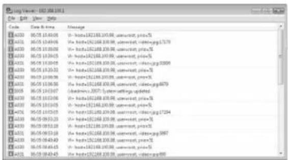
text_image
log version: 102.368.100.1 File Edit View Help Code Date & Time Message 14320 06/05 10:45:06 V - hxtal=192168.100.00, author=ct, print=5 14321 06/05 10:49:06 V - hxtal=192168.100.00, author=ct, print=pgg1737 14322 06/05 10:50:06 V - hxtal=192168.100.00, author=ct, print=5 14323 06/05 10:50:05 V - hxtal=192168.100.00, author=ct, print=5 14324 06/05 10:50:05 V - hxtal=192168.100.00, author=ct, print=pgg3309 14325 06/05 10:52:33 V - hxtal=192168.100.00, author=ct, print=5 14326 06/05 10:56:38 V - hxtal=192168.100.00, author=ct, print=5 14327 06/05 10:56:36 V - hxtal=192168.100.00, author=ct, print=pgg4879 14328 06/05 10:57:47 V - hxtal=192168.100.00, author=ct, print=5 14329 06/05 10:57:56 V - hxtal=192168.100.00, author=ct, print=5 14330 06/05 10:57:45 V - hxtal=192168.100.00, author=ct, print=5 14331 06/05 10:57:43 V - hxtal=192168.100.00, author=ct, print=5 14332 06/05 10:57:42 V - hxtal=192168.100.00, author=ct, print=5 14333 06/05 10:57:42 V - hxtal=192168.100.00, author=ct, print=5 14334 06/05 10:57:42 V - hxtal=192168.100.00, author=ct, print=5 14335 06/05 10:57:42 V - hxtal=192168.100.00, author=ct, print=5 14336 06/05 10:57:42 V - hxtal=192168.100.00, author=ct, print=5 14337 06/05 10:57:42 V - hxtal=192168.100.00, author=ct, print=5 14338 06/05 10:57:42 V - hxtal=192168.100.00, author=ct, print=5 14339 06/05 10:57:42 V - hxtal=192168.100.00, author=ct, print=5 14340 06/05 10:57:42 V - hxtal=192168.100.00, author=ct, print=5 14341 06/05 10:57:42 V - hxtal=192168.100.00, author=ct, print=5 14342 06/05 10:57:42 V - hxtal=192168.100.00, author=ct, print=5 14343 06/05 10:57:42 V - hxtal=192168.100.00, author=ct, print=5 14344 06/05 10:57:42 V - hxtal=192168.100.00, author=ct, print=5 14345 06/05 10:57:42 V - hxtal=192168.100.00, author=ct, print=5 14346 06/05 10:57:42 V - hxtal=192168.100.00, author=ct, print=5 14347 06/05 10:57:42 V - hxtal=192168.100.00, author=ct, print=5 14348 06/05 10:57:42 V - hxtal=192168.100.00, author=ct, print=5 14349 06/05 10:57:42 V - hxtal=192168.100.00, author=ct, print=5 14350 06/05 10:57:42 V - hxtal=192168.100.00, author=ct, print=5 14351 06/05 10:57:42 V - hxtal=192168.100.00, author=ct, print=5 14352 06/05 10:57:42 V - hxtal=192168.10O. . . . . . . . . . . . . . . . . . . . . . . . . . . . . . . . . . . . . . . . . . . . . . . . . . . . . . . . . . . . . . . . . . . . . . . . . . . endAdmin Viewer ( P. 3-6)
This viewer is used by the camera's Administrator. It provides privileged functions not available in VB Viewer, such as camera control, exposure, white balance and external device output.

text_image
http://126.108.193-138 - Xiaobao Internet Explorer http://126.108.193-138 - Xiaobao Internet Explorer 文件(F) 编辑(E) 查看(V) 帮助(H) 控制面板 控制面板 7:10:00:00 7:10:00:00 7:10:00:00 7:10:00:00 7:10:00:00 7:10:00:00 7:10:00:00 7:10:00:00 7:10:00:00 7:10:00:00
Note
Regardless of the settings under "Regional and Language Options" in the Windows Control Panel, a "." is always used for decimal points in numbers. Dates are displayed in "YYYY/MM/DD" or "MM/DD" format, and time in "HH:MM:SS" format.
* Y, M, D, H, M, and S represent year, month, day, hour, minute, and second respectively.
How to Launch
- Double-click the [VBAdmin Tools v5.1] icon on the desktop, or click the [Start] menu, click [Programs], click [WebView Livescope], and then select [VBAdmin Tools v5.1].
Starting from the Desktop Icon Or starting from the [Start] menu

VBAdmin Tools v5.1
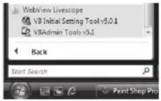
text_image
WebView Livescope VB Initial Setting Tool v5.0.1 VBAdmin Tools v5.1 Back Start Search Paint Shop Pro- The dialog box for specifying the camera to connect to appears.
To use VBAdmin Tools, you must connect to the camera first. Enter each item and then click [OK].

text_image
Connection settings Camera information Host name: 192.168.100.1 User name: root Password: **** HTTP port: 80 Setting page URI http://192.168.100.1/ adults Proxy Use HTTP proxy server Host name: Port: 8080 Load proxy information FTP Use PASV mode OK Cancel (1) (2) (3) (4) (5) (6) (7)(1)Host name ( P. 1-8, P. 1-10)
Specify the IP address or host name of this camera.
(2)User name
Enter the Administrator account "root" set for the camera.
(3)Password ( P. 1-7)
Enter the Administrator password (the factory setting is "camera").
(4)HTTP port ( P. 1-31)
The default is [80].
(5)Setting page URI
The setting URI set for this camera is fixed to "admin" and cannot be changed.
(6)Proxy
* For the proxy settings, check with your Network Administrator.
• [ Use HTTP proxy server]
Select this check box to connect to the camera via a proxy server.
- [ Host name]
Specify the host name or IP address of the proxy server.
• [ Port]
Enter the port number of the proxy server (default = [8080]).
• [ Load proxy information]
When this button is clicked, the proxy server information set by Internet Explorer will be imported automatically.
(7)FTP
Not used with this camera. This function can be used with VB-C50i or earlier cameras.
To use Log Viewer of VBAdmin Tools, the camera must establish FTP connection first. You can select PASV or PORT as the FTP connection mode.
- [ Use PASV mode]
Select this check box if you want to use the PASV mode. Normally the PASV mode should be used. If this check box is cleared, connection will be made in the PORT mode.
3. VBAdmin Tools launches.
You can click the button for each of the three tools to launch [Motion Detection Setting Tool], [Log Viewer] or [Admin Viewer].

text_image
VBAadmin Tools File Help Host name 192.168.100.1 Setting tools Motion Detection Setting Tool Viewers Log Viewer Admin Viewer EditIf the connection has been cut off, etc., select [Connect] from [File] in the menu bar to open the [Connection settings] dialog box.

text_image
VBAdmin Tools File Help Connect... Exit
Note
Notes on Use with Windows Vista/XP
If the [Windows Security Alert] dialog box appeared, click [Unblock].
Once this button is clicked, this warning dialog box will no longer appear.

Note
If connection is made by entering the IPv6 address, Admin Viewer cannot be used on Internet Explorer 6.

Tip
If other Canon network camera is connected, the available tools will change.
This tool is used to set the motion detection function that performs upload, notifies the viewer, records a log, etc., if a change has occurred in the captured image due to movement of a subject. You can set the position and size of the motion detection area, detection judgment conditions, etc., while checking the image on the camera.
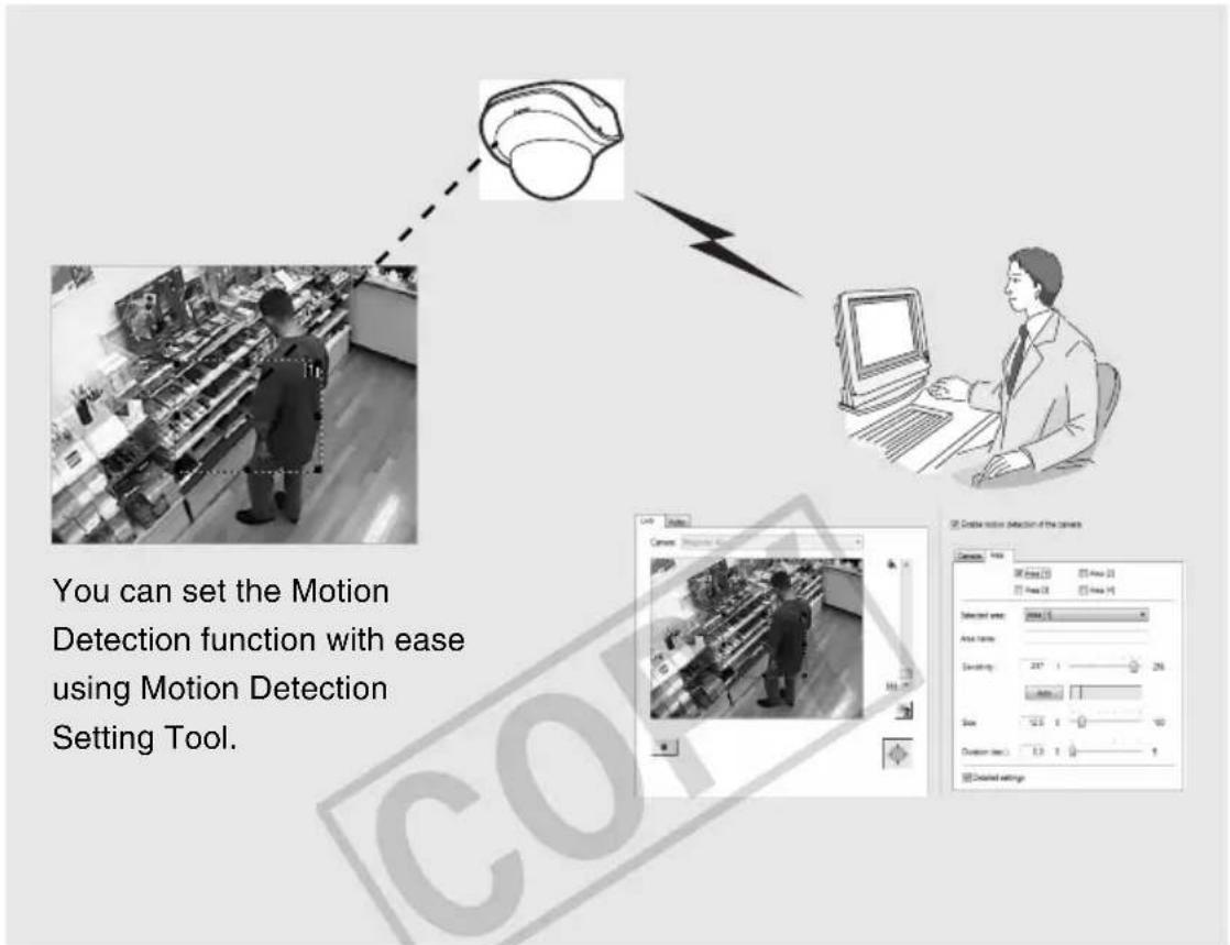
text_image
You can set the Motion Detection function with ease using Motion Detection Setting Tool.The Motion Detection function determines the following items to specify when the camera mode should change to [Detected] and the specified operations such as event upload should be performed, upon change in the viewer image inside the motion detection area: (1) [Sensitivity] indicating the degree of change, (2) [Size] indicating the ratio of the changed area, and (3) [Duration] indicating how long the change continues.
Caution
Notes on Use of This Camera
The Motion Detection function is not suitable in applications where high reliability is required. If high reliability is always required for monitoring, etc., it is recommended that you don't use this function. Canon shall assume no liability for any accident, loss or other undesirable outcomes resulting from operating the motion detection function.
■ Display Screen of Motion Detection Setting Tool (Live Mode)
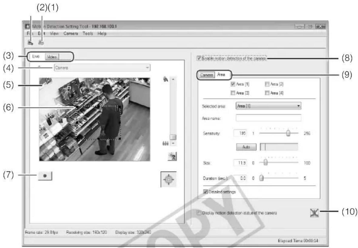
text_image
(2)(1) Motion Detection Setting Tool - 192.168.100.1 File Edit View Camera Tools Help (3) Live Video (4) Camera (5) (6) (7) Enable motion detection of the camera Camera Area Area (1) Area (2) Area (3) Area (4) Selected area: Area (1) Area name: Sensitivity: 190 1 250 Auto Size: 11.5 0 100 Duration (sec): 0.0 0 5 Detailed settings Display motion detection status of the camera Frame rate: 29.8 fps Receiving size: 180x120 Display size: 320x340 Elapsed Time 00:00:14(1) [Load Motion Detection Settings] button
Clicking this button loads the current motion detection settings of the camera.
(2) [Save Motion Detection Settings] button
Clicking this button saves the motion detection setting edited by this tool.
If you have set motion detection, be sure to save the settings using [Save Motion Detection Settings].
(3) Live mode tab (Live/Record)
• [ Live ]
Video is displayed and the camera is controlled. The displayed video is also recorded.
• [Video ]
You can set motion detection judgment conditions while playing the recorded video.
For the specific screen views and operating procedures, see P. 2-16.
(4) Camera Selection box
The name of the connected camera is shown.
(5) Viewer
Video is displayed and the camera is controlled.
(6) Motion detection area frame
The range in which motion detection is performed is shown by a dotted-line frame. You can drag the mouse to resize/move the frame.
(7) [Start recording] button
Clicking this button starts recording video.
(8) [Enable motion detection of the camera]
Select this check box if you want to enable the motion detection function.
(9) Settings tabs (Camera/Area)
- [ Camera ]
Set the frame rate ( P. 2-10).
• [Area]
Select the motion detection area and the sensitivity, size and duration for each area. For the specific screen views and operating procedures, see P. 2-11.
(10) [Display motion detection status of the camera]
Selecting this check box displays the motion detection status of the camera. You can check if the settings are enabled on the camera ( P. 2-13).
■ Flow of Motion Detection Setting
The motion detection function is set according to the procedure below. For details on the setting method, see each setting page.
- Launches Motion Detection Setting Tool.
The Motion Detection Setting Tool window appears ("Display Screen of Motion Detection Setting Tool (Live Mode)") (→ P. 2-8).
Set motion detection in the Settings tab on the right side of the screen. The Settings tab has two tabs: [Camera] and [Area].
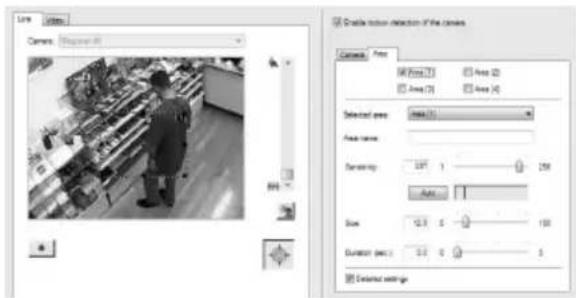
text_image
Line Camera: Compound 41 Create motion detection if the camera Camera: None View: Area 0 Area 1 Area 2 Area 3 Selected area: Area 0.1 Face name: Detuning: 297.1 Size: 0.3 Duration (sec): 0.0 Evolved settings-
Set the frame rate for motion detection ([Camera] tab, → P. 2-10).
-
Set the detection area ([Area] tab, → P. 2-11)
-
Set the conditions specifying the degree of change triggering the [Detected] mode ([Area] tab, → P. 2-11).
5. Save the settings.

Tip
- The Motion Detection Setting Tool viewer window shows 160x120 black & white image regardless of the camera settings.
- In the [Area] tab, you can set the [Detected] judgment conditions for each area while checking the viewer image on the left side of the screen. For the applicable display screen, etc., see "[Detected] Mode and Display Screen" (→ P. 2-14). You can also set judgment conditions while playing the recorded video in the [Live] tab (→ P. 2-16).
● Motion Detection function - When setting this function, confirm that detection will actually be performed correctly.
- If the subject is moving fast or the entire image is dark, motion detection may not operate correctly.
- If a change occurs due to light, wind, etc., false detection may occur.
■ Setting Motion Detection
How to Set
1. Enable motion detection.
Select the [Enable motion detection of the camera] check box.
2. Set the frame rate for motion detection ([Camera] tab).
When this check box is selected, the camera's frame rate for motion detection can be changed. Enter a desired value from 0.5 up to 30.0 fps.
![CANON VB-C500D - Set the frame rate for motion detection ([Camera] tab). - 1](/content/2026/06/1214332/images/4dcb8b2932bd60f98164ed22b9859e4fbb9e7d4e0803c0b027ddd63b337abf9b.jpg)
text_image
Enable motion detection of the camera Camera Area Enable frame rate setting Set the frame rate to: 30.0 fps (0.5 to 30.0)![CANON VB-C500D - Set the frame rate for motion detection ([Camera] tab). - 2](/content/2026/06/1214332/images/a33caacd361537dc51487dad7f982ea2ba2f8e4313956861b054a2e504ebe148.jpg)
Note
The value set in [Maximum Frame Rate: Image Transmission] ( P. 1-18) must be greater than the frame rate set by this tool.

Tip
- If the network load is heavy, the specified frame rate may not be achieved.
- By setting a lower frame rate, the video extracted from the captured video will be included in the scope of motion detection. This way, you can also perform motion detection for slow-moving subjects, etc.
● The frame rate set here is applied only to motion detection.
3. Set the motion detection area ([Area] tab).
Up to four motion detection areas can be created, where the frame of each area can be resized/moved by dragging. To resize the frame, drag "■" at four corners/on four sides. To move the frame, drag a point inside the frame. You can also set a separate motion detection level for each area. This camera lets you set the motion detection level while playing the video recorded in the [Live] tab (→ P. 2-16).
![CANON VB-C500D - Set the motion detection area ([Area] tab). - 1](/content/2026/06/1214332/images/d649e6a93aa42d4cc43262fe71d6256476ce306ae6779a8fdb1d7c95e1fd07ad.jpg)
text_image
Live Video Camera: Register 61 Enable motion detection of the camera Camera Area Area [1] Area [2] Area [3] Area [4] Selected areas: Auto [1] Area name: Sensitivity: 237 1 256 Auto Size: 12.5 0 100 Duration (sec): 0.0 0 5 Detailed settings (1) (2) (3) (4) (5) (6) (7) (8)(1)[Motion Detection Area]
Select the check box corresponding to the motion detection area you want to use, and the detection area frame will be displayed in the viewer. Up to four detection areas can be created.
(2)[Selected Area]
If multiple motion detection area frames have been created, a separate motion detection level can be set for each area frame.
Set the area name for the selected area below. (Area name can also be omitted.)
Up to 15 ASCII characters (spaces or printable characters) can be used for the [Area name].
(3)[Sensitivity]
Set the sensitivity of motion detection in a range of 1 to 256. Set a desired value by dragging the slide bar. The greater the value, the higher the detection sensitivity becomes.
(4)[Auto] button
Clicking [Auto] allows the sensitivity to be set automatically at which the mode will change to [Detected] when a change occurs in the image shown inside the motion detection area. Click this button when nothing is moving.
(5) Detection Indicator
The level of the motion detected by the camera is shown in a graph in real time ( P. 2-15).
(6)[Size]
The camera mode will change to [Detected] if the ratio of the area in which change has been detected (red or yellow rectangle) to the area of the selected detection area frame (frame indicated by blue solid lines) exceeds the value set here ( P. 2-14). However, the mode will not change to [Detected] even when the set value of [Size] has been exceeded, if the change has not continued for the duration in seconds set in [Duration]. Set a desired value in a range of 0 to 100% by dragging the slide bar.
(7) Duration
The camera mode will change to [Detected] if the change occurring in the image inside the detection area has satisfied the conditions set in (3) [Sensitivity] and (6) [Size] for the duration set in [Duration].
Normally [Duration] is fixed to [0.2] . If the [Detailed Settings] check box is selected, however, you can set a desired value in a range of 0 to 5 seconds by directly entering a value or dragging the slide bar.
(8)[Details]
When this check box is selected, you can enter [Sensitivity], [Size] and [Duration] values. If the check box is not selected, [Duration (sec.)] is fixed to [0.2].
![CANON VB-C500D - (8)[Details] - 1](/content/2026/06/1214332/images/6ac900a6e935e04e9da7e1ed5810522cb0a0e0108011a90c62a0df70ace96162.jpg)
Tip
- Even when a change has occurred in the image shown inside the viewer's motion detection area frame, the camera will not recognize it as [Motion] if the [Sensitivity] setting is low. Even when the sensitivity is raised, the camera mode will not change to [Detected] unless the part of the area frame that has moved meets the [Size] and [Duration] settings for motion.
- You can also select the setting area by clicking a desired motion detection area frame in the viewer. The selected detection area frame is shown by blue solid lines.
- By setting the Selected areta to [Not specified], you can show the detection statuses for all motion detection areas at once. Clicking a point in the viewer where no area frame is set has the same effect.
4. Check the motion detection status of the camera.
To check the level of motion detection operation based on the specified settings, select the [Display motion detection status of the camera] check box. The motion detection status will be shown by the icons specified below.
If the [Display motion detection status of the camera] check box is selected, the settings cannot be selected. To save the settings, clear this check box.

[Detection disabled]
☑ Display motion detection status of the camera Not detected

[Detected]

[Not detected]

Note
- If a proxy server is used, the video frame rate may drop depending on the proxy load. Accordingly, it is recommended that you don't connect the camera via a proxy while this function is set.
- It is recommended that the motion detection level be set in a condition as close as possible to the condition in which the camera is actually used.

Tip
- The status of the detection in peak block view and [Display motion detection status of the camera] in this tool may not match the actual motion detection status of the camera.
- When the motion detection function of the camera is enabled, the video frame rate may drop compared to when the function is disabled.
-
Clicking [Edit] in the menu bar and selecting [Copy sensitivity settings] copies the settings of [Sensitivity], [Size] and [Duration] for the currently selected area (1 to 4). If a different area (1 to 4) is subsequently selected and [Paste sensitivity settings] is selected from [Edit] in the menu bar, the copied settings will be pasted to the selected area.
-
Click [Save Motion Detection Settings] to save the settings.

Tip
[Detected] Mode and Display Screen
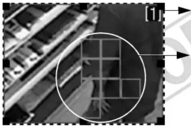
natural_image
Aerial view of a building complex with a highlighted grid pattern and directional arrows (no readable text or symbols)The area frame in which the camera is detecting motion is displayed by blue solid lines in the viewer.
The area in which the camera is detecting motion at the specified sensitivity is displayed by a yellow or red rectangle inside the motion detection area frame.
Yellow rectangle: The camera detected a motion, but it did not meet the [Size] or [Duration] setting and thus the mode has not changed to [Detected].
Red rectangle: The camera detected a motion, but it met the [Size] or [Duration] setting and thus the mode has not changed to [Detected].
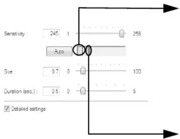
text_image
Sensitivity : 245 1 256 Auto Size : 9.7 0 100 Duration (sec.) : 0.5 0 5 Detailed settingsIf a change occurred in the image, the value set in [Size] is shown by a vertical bar on the indicator. The following two indicator colors are used.
Green : The area of the motion detected by the camera does not meet [Size].
Yellow : The area of the motion detected by the camera meets [Size].
Peak block
A red peak block will be displayed when both the [Size] and [Duration] conditions are satisfied and the camera mode changes to [Detected]. Set the motion detection level while checking when a peak block is actually displayed at a given level of motion.
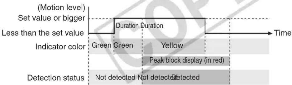
other
| Time Segment | Color | Event Description | | ------------------------ | --------- | ------------------------------------- | | Start | Green | Not detected | | Mid-End | Green | Not detected | | End | Yellow | Peak block display (in red) | | End | Yellow | Detected |If a motion corresponding to [Size] or greater has remained detected for the specified duration or longer, the mode changes to [Detected] and a peak block is displayed. Even when the specified size becomes no longer met in the [Detected] mode where a peak block is still displayed, the [Detected] mode will be maintained for the specified duration.

Tip
Setting the Motion Detection Sensitivity While Checking the Recorded Video
To set the motion detection level at which the camera mode will change to [Detected], you can adjust the settings while checking the actual motion in the viewer. The camera lets you set a desired motion detection level while playing the live video recorded in the Live tab ( P. 2-8), so you need not repeat the actual motion in front of the camera.
* If you are using Windows Vista without SP1, recording by Motion Detection Setting Tool may not be possible.
- Selecting [Video recording options] from [Tools] in the menu bar opens the Video recording options dialog box.
Video recording options dialog box

text_image
Video recording options Maximum recording time : 180 sec. (60 to 300) Self-timer : 0 sec. (0 to 30) OK Cancel(1)[Maximum recording time]
Set the maximum recording time. Set a desired value in a range of 60 to 300 seconds.
(2)[Self-timer]
Set the time after clicking the Rec.Start button when recording will be started. Set a desired value in a range of 0 to 30 seconds.
- Adjust the camera position and click the Rec.Start button in the [Live] tab.

Recording 00:04 / 03:00 (Max.)
Recording of the video shown in the viewer will start. Record the video needed to adjust the motion detection level by creating motion in front of the camera.
To stop recording, click the Stop button.
- Adjust the motion detection sensitivity in the [Area] tab while checking the video in the [Video] tab.
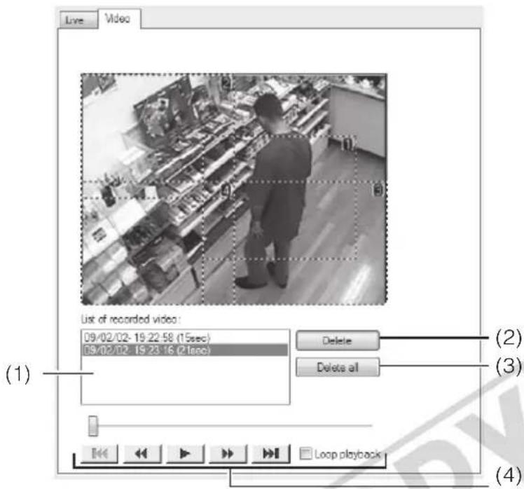
text_image
Live Video List of recorded video: 09/02/02-19:22:58 (15sec) 09/02/02-19:23:16 (21sec) Delete Delete all Loop playback (1) (2) (3) (4)(1)List of recorded video
A list of recorded video is shown.
(2)[Delete] button
Clicking this button deletes the video selected from the list of recorded videos.
(3)[Delete All] button
Clicking this button deletes all videos shown in the list of recorded videos.
(4) Control buttons
The available buttons are "Move to Start", "Rewind", "Play", "Fast Forward" and
"Move to End" from the left.
When the [Loop playback] check box is selected, the video is played repeatedly.
This viewer lets you view the operating condition log of the camera.

text_image
Log Viewer -192.168.100.1 File Edit View Help Code Date & time Message A030 06/05 10:49:06 W- host=192.168.100.99, user=root, prio=51 A031 06/05 10:49:06 Ww host=192.168.100.99, user=root, video.jpg17170 A030 06/05 10:39:09 W- host=192.168.100.89, user=root, prio=51 A030 06/05 10:39:05 W- host=192.168.100.89, user=root, prio=51 A031 06/05 10:39:05 Ww host=192.168.100.89, user=root, video=jpg32990 A030 06/05 10:39:33 W- host=192.168.100.89, user=root, prio=51 A030 06/05 10:36:56 W- host=192.168.100.89, user=root, prio=51 A031 06/05 10:36:56 Ww host=192.168.100.89, user=root, video.jpg6879 SXX5 06/05 10:33:07 (badmin.c.2007) System settings updated A030 06/05 10:33:06 W- host=192.168.100.89, user=root, prio=51 A030 06/05 10:33:05 W- host=192.168.100.89, user=root, prio=51 A031 06/05 10:33:03 Ww host=192.168.100.89, user=root, video.jpg17294 A030 06/05 10:33:38 Ww host=192.168.100.89, user=root, prio=51
Tip
- Log Viewer only has a log viewing function and logs cannot be deleted.
- Logs are saved by selecting [Save] from [File] in the menu bar. Logs can be saved in the text format.
Downloading Log Files
How to Download
Launch Log Viewer from VBAdmin Tools, and the latest log files will be downloaded and displayed automatically. To download a new log file list, select [Download] from [File] in the menu bar.
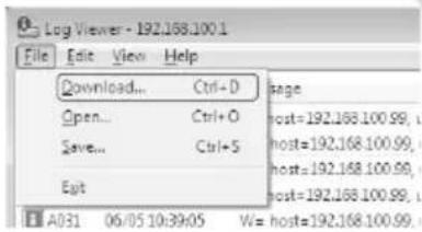
text_image
Log Viewer - 192.168.100.1 File Edit View Help Download... Ctrl+D Open... Ctrl+O Save... Ctrl+5 Eat page host=192.168.100.99, host=192.168.100.99, host=192.168.100.99, host=192.168.100.99, host=192.168.100.99, A031 06/05 10:39:05 W= host=192.168.100.99When the list has been downloaded, a dialog box showing the log file list opens. Select the log file you want to view and click [Download], and the selected log file will be downloaded.
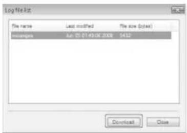
text_image
Log Nekt File name Last modified File size (fold) mssages Jul 01 07:49:08.2008 5412 Download CloseViewing Logs
The log contains the following information.
Code
The log code is shown. For the log code, see "List of Log Messages" ( P. 5-7).
The log code is shown together with one of three icons corresponding to the applicable level. If the log has no log code, no icon is shown.

Information level

Error level

Warning level
- Date and Time
The date and time at which the log was generated is shown.
- Message
A message regarding the log is shown.
■ Saving a Log to a File/Opening a Saved Log
You can save the displayed log to a file or view a log file saved before.
How to Save
Select [Save] from [File] in the menu bar.

text_image
Log Viewer - 192.100.100.1 File Edit View Help Download... Ctrl+D Open... Ctrl+O Save... Ctrl+S Exit stage host=19 host=1 host=1 host=19 A031 06/05 10:39:05 W= host=1How to View
Select [Open] from [File] in the menu bar and then select the log file you want to view.
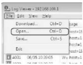
text_image
Log Viewer - 192.168.100.1 File Edit View Help Download... Ctrl+D Open... Ctrl+O Save... Ctrl+S Exit 4031 06/05 10:39:05 We host=1 2021 06/05 10:39:05■ Copying/Searching Logs
You can copy the displayed log or search logs.
How to Copy
Click to select the log you want to copy, and then select [Copy] from [Edit] in the menu bar.
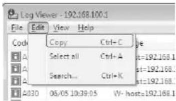
text_image
Log Viewer - 192.168.100.1 File Edit View Help Code Copy Ctrl+C Select all Ctrl+A Search... Ctrl+K A4030 06/05 10:39:05 W-host=192.168.1How to Search
- Select [Search] from [Edit] in the menu bar.
The Search dialog box appears.
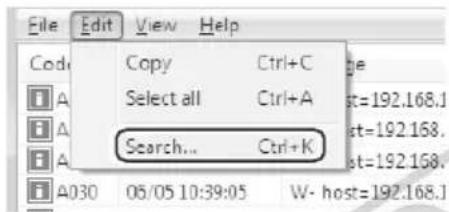
text_image
File Edit View Help Code Copy Ctrl+C ge Select all Ctrl+A st=192.168.1 Search... Ctrl+K st=192.168. A030 05/05 10:39:05 W- host=192.168.- Enter a desired character string, and then click [Search].
■ Showing All Logs
How to Display
Select [Show all logs] from [View] in the menu bar.
All event logs are shown, including the logs specified in the log message list ( P. 5-7), just like when [View Log Events] ( P. 1-47) is selected from [Maintenance] on the setting page.
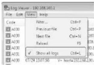
text_image
Log Viewer - 192.108.100.1 File Edit View Help Code Filter Ctrl+P A030 Previous File Ctrl+P 100 A030 Next file Ctrl+N 200 A030 Railroad FS 100 A030 ✓ Show all logs Ctrl+L 00 A030 07/24 13:07:55 V+ host=192.168.100■ Showing Filtered Logs
You can filter logs by type, code and date & time to show only the necessary information.
How to Set
- Select [Filter] from [View] in the menu bar.

text_image
Log Viewer - 192.168.100.1 File Edit View Help Code Filter... Ctrl+F A030 Previous File Ctrl+P A031 Next file Ctrl+N A030 Reload F3 A030 Show all logs Ctrl+L A030 05/03/10:20:23 + host=192.168.100.1- The Filter dialog box appears.
Setting the following conditions and clicking [OK] shows only the logs matching the specified conditions.
To cancel filtering, click [Cancel].
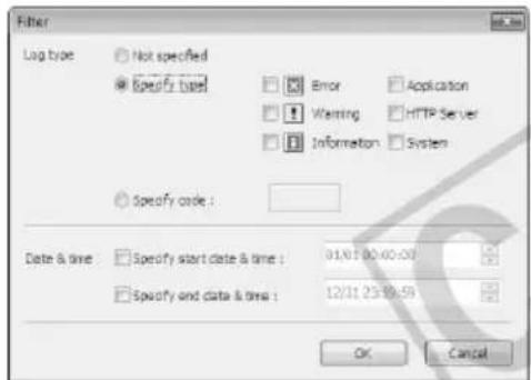
text_image
Filter Log type Not specified Specify type Error Application Warning HTTP Server Information System Specify code : Date & time Specify start date & time : 01/07/00:00:00 Specify and data & time : 12/31/23:39:59 OK Cancel[Log type]
Select the [Specify type] or [Specify code] check box to filter logs by type. If you don't want to filter logs by type, select [Not specified]. Logs without log code are shown with [Not Specified] selected, when [Show All Logs] is selected from [View] in the menu bar.
- Specify type
Specify the log level
Select the level of logs to be displayed from among [Error], [Warning] and [Information].
Specify log output module
Select the output source module whose logs will be displayed, from among [Application], [HTTP Server] and [System].
- Specify code
Specify the log code. The entered characters are compared against all logs and only the logs matching the code are displayed. If "A0" is entered, for example, logs starting with 'A0' are displayed.
[Date and Time]
● [Specify start date & time]
When this check box is selected and a date and time is entered, logs generated on or after the specified date and time are displayed.
● [Specify end date & time]
When this check box is selected and a date and time is entered, logs generated on or before the specified date and time are displayed.
![CANON VB-C500D - [Date and Time] - 1](/content/2026/06/1214332/images/69256640054cd836b1c54f48af873725659d686329321facd8b1067aecd32f75.jpg)
Tip
[Application], [HTTP Server] and [System] support the log message list ( P. 5-7).
3
VB-C500 Viewer
The following explains VB-C500 Viewer that lets you access the camera using a web browser to display live video, zoom of the camera, control the exposure, control the night mode, adjust the white balance, and control the smart shade control function, among others.
VB-C500 Viewer is a viewer that lets you access the network camera VB-C500VD/VB-C500D via a web browser to display image and operate the camera via zoom control, etc.
Two types of viewers, Admin Viewer and VB Viewer, are available for VB-C500 Viewer.
VB-C500 Viewer
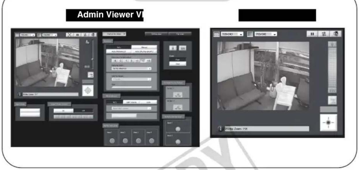
text_image
Admin Viewer VI 320x40 920x40 120 Box Zoom: 153
Note
Use VK-Lite Viewer to display MPEG-4 video from the camera.
Only JPEG video can be displayed using the built-in VB-C500 Viewer.
Major Differences Between Admin Viewer and VB Viewer
● The operable ranges are different.
Admin Viewer : In addition to displaying video from the camera, you can use the basic camera controls such as zoom operations as well as an administrative control functions such as exposure and white balance.
VB Viewer : You can only display video from the camera and access basic camera controls such as zoom operations.
- Accessible controls are different.
Admin Viewer : Users with the Privileged Camera Control can use this viewer.
Password authentication is required.
Authorized users must have the Privileged Camera Control assigned by the Administrator beforehand ( P. 1-38).
VB Viewer : Users with the Camera Control can use this viewer.
You can set the applicable options to enable/disable password authentication or limit zoom controls of the camera, etc. (→ P. 1-38).
User Authorities and Camera Control Privileges
The relationships of user authorities and camera control privileges are specified below.
| User authority | Camera control privileges | Image Distribution | Audio Distribution | |
| Privileged Camera Control | Camera Control | |||
| Administrator ○ | ○ | ○ | ||
| Authorized users | ○(Can be changed) | ○(Can be changed) | ○(Can be changed) | ○(Can be changed) |
| Guest user × | ○(Can be changed) | ○(Can be changed) | ○(Can be changed) | |
* Can be changed: The Administrator can change a given authority of an authorized user or guest user.
The user can have four authorities including Privileged Camera Control, Camera Control, Image Distribution and Audio Distribution.
To use Admin Viewer, the user must have the Privileged Camera Control.
To display video using VB Viewer, the user must have the Image Distribution. To also operate the camera using VB Viewer, the user must have the Camera Control, as well.
The Audio Distribution authority is required to receive audio using Admin Viewer and VB Viewer.
[Administrator]
This user has all authorities. The user name is fixed to "root."
The Administrator can launch Admin Viewer from the [Admin Viewer] link on the top page.
[Authorized User]
The authorized user can launch Admin Viewer from the [Admin Viewer] link on the top page if he/she has the Privileged Camera Control. Upon losing the Privileged Camera Control, the authorized user can no longer launch Admin Viewer. However, he/she can still launch VB Viewer. Launching of VB Viewer by a given authorized user can be prohibited by disabling all authorities of the user ( P. 1-38).
[Guest User]
This user can only perform zoom controls of the camera, backlight compensation, video display and audio distribution.
The guest user can launch VB Viewer from the [VB Viewer] link on the top page. The Administrator can prevent all camera accesses by a guest user by disabling all authorities of the user.
![CANON VB-C500D - [Guest User] - 1](/content/2026/06/1214332/images/fa78558fb16e4f250ad5bc2ada40c43bf799014e912f3c9080745e6018d2fe5c.jpg)
Note
- Admin Viewer launched by an [Administrator] can take over the camera control privileges from Admin Viewer launched by an [Authorized User] at any time. The Administrator can retain the camera control privileges, in which case authorized users cannot obtain the camera control privileges. After viewing the necessary information, the Administrator should always close the viewer or click "Obtain/release Camera Control" to release the control privileges.
- Admin Viewer launched by an [Administrator] can access only one camera at a time. If one user is accessing the camera from a given PC with the Administrator authorities, other users cannot access the camera from other PCs with the Administrator authorities. On the other hand, Admin Viewer launched by an [Authorized User] allows the camera to be accessed from multiple PCs at the same time. Take note, however, that if the camera is to be controlled, the control privileges are given to the user who accessed the camera last.

Tip
● The factory setting is to also give the Privileged Camera Control to [Authorized User].
- If all authorities of a guest user are disabled, the user authentication dialog box will appear when the user launches VB Viewer. When an authorized user or Administrator name and password are entered, a guest user can use VB Viewer based on the authorized user or Administrator authorities.
● List of Authorized User Authorities
The authorities of authorized users are assigned as follows.
List of Authorized User Authorities
| Provided controls Viewer | Operations | |
| Privileged Camera ControlCamera ControlImage DistributionAudio Distribution | Admin Viewer(Viewer Screen) | Zoom operation of the camera, On/Off switch of backlight compensation, image display size switch, Audio button operation, Reconnect button operation, full screen mode and pausing video |
| Admin Viewer(Administrator Control Screen) | Operations in [Control for Admin] display screenDetailsCamera zoom speed/operation, Smart Shade Control, exposure, white balance, Night mode, detection display of external device input, detection display of motion detection area, external device output control | |
| VB Viewer | Operations in VB ViewerDetailsZoom operation of the camera, On/Off switch of backlight compensation, image display size switch, Audio button operation, Reconnect button, operation and pausing video | |
| Camera ControlImage DistributionAudio Distribution | VB Viewer | Operations in VB ViewerDetailsZoom operation of the camera, On/Off switch of backlight compensation, image display size switch, Audio button operation, Reconnect button, operation and pausing video |
| Image DistributionAudio Distribution | VB Viewer | Changing video display size, switching on/off of audio reception, reconnecting to the camera, pausing/resuming video* The User Authentication dialog box is displayed when clicking the camera control button. Users can control the camera by entering the Administrator's user name and the password in the dialog box. |
| Image Distribution | VB Viewer | Changing video display size, reconnecting to the camera, pausing/resuming video |
* If the image distribution authority is disabled, the applicable user can no longer use VB Viewer.
Launching VB-C500 Viewer
The various settings of VB-C500 Viewer are specified by accessing the camera via a web browser. First, access the Settings title page.

Note
This document explains relevant operations based on the IP address "192.168.100.1" (factory setting). In reality, the customer must enter the IP address set for the camera.
How to Launch
- Access "http://192.168.100.1/" in the web browser.
- Click [Admin Viewer] or [VB Viewer] according to the user.
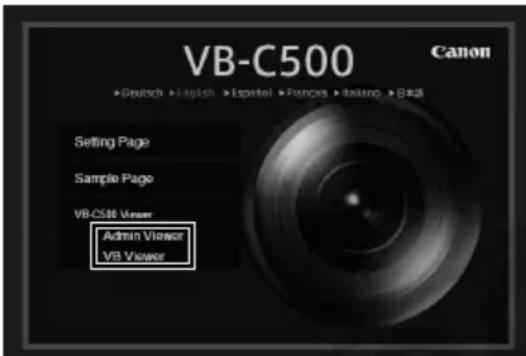
text_image
VB-C500 Canon ►Deutsch ►English ►Español ►Pances ►Italano ►B281 Setting Page Sample Page VB-C500 Viewer Admin Viewer VB Viewer- If [Admin Viewer] has been clicked, enter the user name and password.
The factory settings are as follows ( P. xiii):
User name: root
Password: camera
The user name "root" is the Administrator account for the camera.
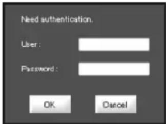
text_image
Need authentication. User : Password : OK Cancel* The password is "camera." Be sure to change them on the [Network] setting page ( P. 1-7).
- VB-C500 Viewer launches.
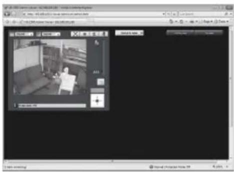
text_image
Screenshot of a video editing software interface showing a grayscale image with a person sitting on a couch, displayed in a window with Chinese UI elements.Shutting Down VB-C500 Viewer
How to Shut Down
Close the web browser in the viewer to shut down.
Connecting from VBAdmin Tools
Only the Administrator can connect to this viewer.
How to Launch
- Launch VBAdmin Tools.
For information on how to launch VBAdmin Tools, see "Launching VBAdmin Tools" (→ P. 2-4) in "Chapter 2 VBAdmin Tools".
- Click [Admin Viewer].

text_image
VBAadmin Tools File Help Host name 192.168.100.1 Setting tools Motion Detection Setting Tool Viewers Log Viewer Admin Viewer Exit3. Enter the user name and password.
The factory settings are as follows ( P. xiii):
User name: root
Password: camera
The user name "root" is the Administrator account for the camera.
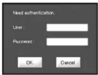
text_image
Need authentication. User: Password: OK Cancel* The password is "camera." Be sure to change them on the [Network] setting page (→ P. 1-7).
4. Admin Viewer launches in the web browser.

text_image
01.00000000000000000000000000000000000000000000000000000000000000 http://www.963.com.cn/Understream Engine File Edit View Tools Help Add to Web Add to Web Add to Web Add to Web Add to Web Add to Web Add to Web Add to Web Add to Web Add to Web Add to Web Add to Web Add to Web Add to Web Add to Web Add to Web Add to Web Add to Web Add to Web Add to Web Add to Web Add to Web Add to Web Add to Web Add to Web Add toWeb
Note
If a wrong user name or password is entered, the camera cannot be connected. Connect the camera by entering the correct user name and password.
Display Screens of Admin Viewer
The following gives an overview of the functions of buttons, boxes and other screen elements displayed when Admin Viewer is launched.
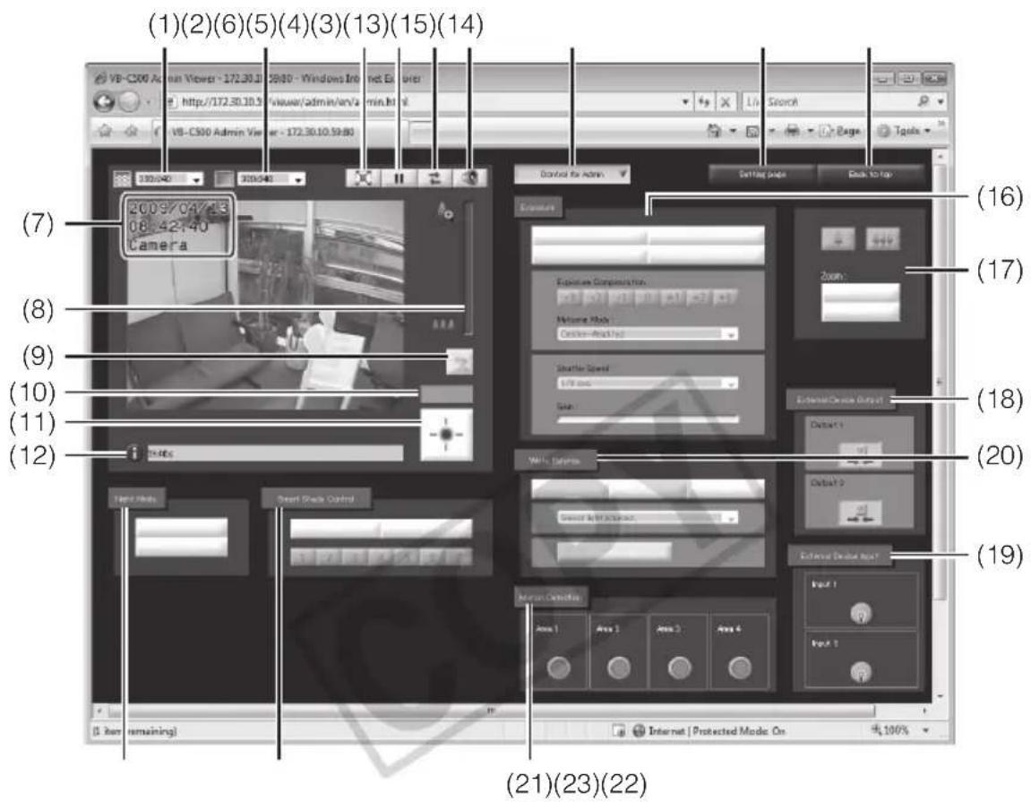
text_image
(1)(2)(6)(5)(4)(3)(13)(15)(14) VB-C500 Admin Viewer - 172.30.31 20:00 - Windows Internet Explorer http://172.30.30.5 viseer/admin/en/a min.html VB-C500 Admin Viewer - 172.30.10.59:00 Control for Admin Setting page Back to top (7) 2009/04/23 08:42:40 Camera (8) (9) (10) (11) (12) 19:46s Face Media Smart Shock Control External Device Output Output 1 Output 2 External Device Output Input 1 Input 2 (16) (17) (18) (19) (21)(23)(22) [5 Box remaining] Internet | Protected Mode On 4x100%(1) Video Capture Size
Set the size of video received from the camera.
(2) Video Display Size
Set the display size of video shown on the screen.
(3) Full Screen Mode button
Live video is shown in the full-screen mode.
(4) Pause/Resume button
Displayed video is paused. Clicking the button again while the video is paused resumes live video.
(5) [Reconnect] button
The camera is reconnected.
(6) Audio Reception button
Audio from the camera is received and output.
(7) On-screen display
Items set to [Enable] in [On-screen display] under [Video] on the Setting page are displayed in the specified position ( P. 1-20).
(8) Scroll bar for zoom
This scroll bar is used to control the zoom ratio.
You can zoom in (show a telephoto view) by moving the knob upward or zoom out (show a wide-angle view) by moving the knob downward.
(9) [Backlight Compensation] button
This button turns on/off backlight compensation. This control is effective when the image is dark due to backlight. Clicking the button again cancels backlight compensation.
(10) Control Privilege Status Indicator
Whether or not the current client has the camera control privileges is shown in this area.
(11) Obtain/release Camera Control button
This button is used to obtain/release the camera control privileges.
(12) Information Filed
Information messages, warning messages and error messages are shown to the user.
(13) [Control for Admin] button
This button is used to show/hide the operation panel for Administrator control.
(14) [Setting Page] button
The screen switches to the Settings Menu page.
(15) [Back to top] button
The screen switches to the top page of the camera.
(16) [Exposure]
You can control the exposure.
(17) [Camera Control] button
You can control the camera zoom. You can also change the zoom speeds.
(18) [External Device Output]
Control the output to an external device.
(19) [External Device Input]
The status of input from an external device is shown.
(20) [White Balance]
You can control the white balance.
(21) [Motion Detection]
The status of motion detection is shown.
(22) [Smart Shade Control]
You can operate the Smart Shade Control.
(23) [Night Mode]
You can switch the Day mode and Night mode.
Display Screens of VB Viewer
The following gives an overview of the functions of buttons, boxes and other screen elements displayed when VB Viewer is launched.
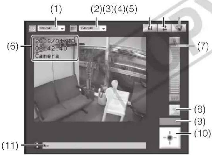
text_image
(1) (2)(3)(4)(5) (6) 2009/04/13 08:42:40 Camera (7) (8) (9) (10) (11)(1) Video Capture Size
Set the size of video received from the camera.
(2) Video Display Size
Set the display size of video shown on the screen.
(3) Pause/Resume button
Displayed video is paused. Clicking the button again while the video is paused resumes live video.
(4) [Reconnect] button
The camera is reconnected.
(5) Audio Reception button
Audio from the camera is received and output.
(6) On-screen display
Items set to [Enable] in [On-screen display] under [Video] on the Setting Menu are displayed in the specified position ( P. 1-20).
(7) Zoom Controller
This bar is used to control the zoom ratio.
(8) [Backlight Compensation] button
This button turns on/off backlight compensation. This control is effective when the image is dark due to backlight. Clicking the button again cancels backlight compensation.
(9) Control Privilege Status Indicator
Whether or not the current client has the camera control privileges is shown in this area.
(10)[Get Camera Control] button
This button is used to obtain the camera control privileges.
(11) Information Filed
Information messages, warning messages and error messages are shown to the user.
Obtaining the Camera Control Privilege
The camera cannot be controlled by multiple users at the same time. Only the user with the control privileges can control the camera. To perform zoom operations, implement backlight compensation or otherwise control the camera, you must obtain the control privileges first.
How to Operate
Click "Obtain/release Camera Control" button to obtain the control privileges.

text_image
Admin Viewer VI Control Privilege Status Indicator The status of camera control privileges is shown. "Obtain/release Camera Control" buttonThis button is used to obtain/release the camera control privileges. * With VB Viewer, you can only obtain the camera control privileges.
■ Camera Control Privilege Status Indicator
How the camera control buttons and Camera Control Status Indicator are shown changes as follows according to the status of control privileges.
Control privileges not assigned Control privileges assigned
The Control Privilege Status Indicator is shown in gray.
The Control Privilege Status Indicator is shown in blue.
Waiting for control privileges Video paused
VB Viewer While you are waiting for control privileges in , the remaining standby time is shown in the Control Privilege Status Indicator.
While video is paused ( P. 3-16), an icon indicating the paused status is shown in the Control Privilege Status Indicator.
Changing the Camera Zoom Ratio How to Operate
Admin Viewer
Move the knob on the scroll bar for zoom in/out.
The camera zoom ratio will change according to the knob position on the scroll bar. You can also move the knob by clicking a blank point on the scroll bar.

text_image
Zoom telephoto end Scroll bar for zoom Move the knob upward to zoom in (show a telephoto view), or move it downward to zoom out (show a wide-angle view). Wide end
Tip
z If [Disable] is set for [Digital Zoom] under [Camera] on the setting page, the zoom scroll bar and icon are grayed out ( P. 1-16)
z You can also operate the zoom using the applicable camera operation buttons ( P. 3-23).
VB Viewer
Click the setting bar for zoom.
The camera zoom ratio will change according to the relative vertical position of the clicked point. You can also operate the zoom by clicking the icons at the top and bottom of the zoom setting bar.

natural_image
Interior view of a modern living room with sofa, bookshelf, and chair (no visible text or symbols)Setting bar for zoom
The top end indicates the upper limit (in a telephoto view), while the bottom end indicates the lower limit (in a wide-angle view).
■ Compensating Backlight
This control is effective when the image is dark due to backlight.
How to Operate
Clicking [Backlight Compensation] brightens the image that was previously dark due to backlight.
Clicking the button again cancels backlight compensation.
Admin Viewer VB
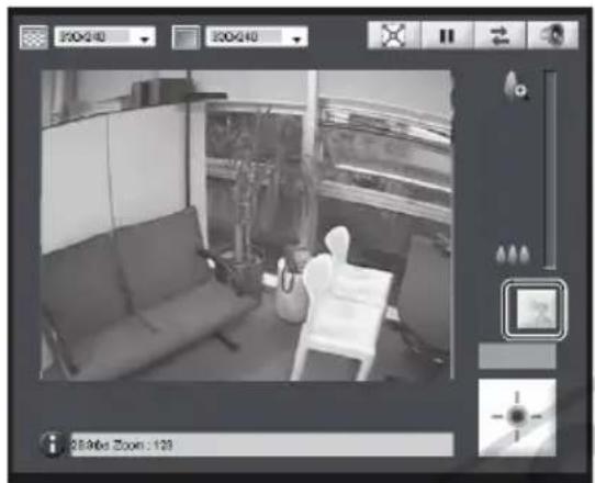
natural_image
Interior view of a room with a person seated on a chair, no visible text or symbols
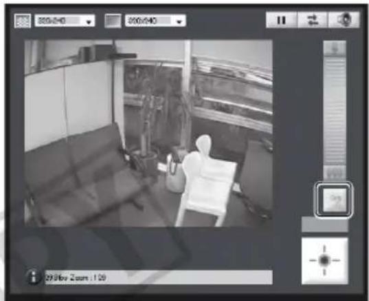
natural_image
Interior view of a room with a person seated in a chair, no visible text or symbols on the main subject.Setting Video and Audio
You can change the video capture size, change the video display screen, show video in the full-screen mode, pause video, reconnect the camera and set audio reception.
Admin Viewer VB

natural_image
Interior view of a modern living room with sofa, coffee table, and wall-mounted screens (no visible text or symbols)

natural_image
Interior view of a modern living room with sofa, chair, and wall-mounted equipment (no visible text or symbols)■ Changing the Video Capture Size
You can set a desired resolution for video received from the camera. Select from [160x120], [320x240] and [640x480].

text_image
320×240 160×120 320×240 640×480■ Changing the Video Display Screen
You can change the video display screen. Select from [160x120], [320x240] and [640x480].
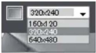
text_image
320x240 160x120 320x240 640x480
Tip
- When the viewer is launched, the video capture size set for the camera is applied (→ P. 1-18).
- When the viewer is launched, the video display size becomes [320x240].
■ Viewing Video in the Full-screen Mode (Admin Viewer Only)
You can show video over the entire display. Click this button, and a new window will open to show video in the full-screen mode.
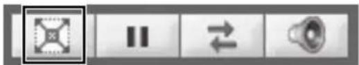
text_image
Screenshot of a software toolbar with icons for playback, bidirectional arrow, and speakerTo close the full-screen display window, click the close button of the window.
■ Pausing/Resuming Video
You can pause/resume video.
Click this button to pause/resume video.
■ Saving the Paused Image
How to Operate
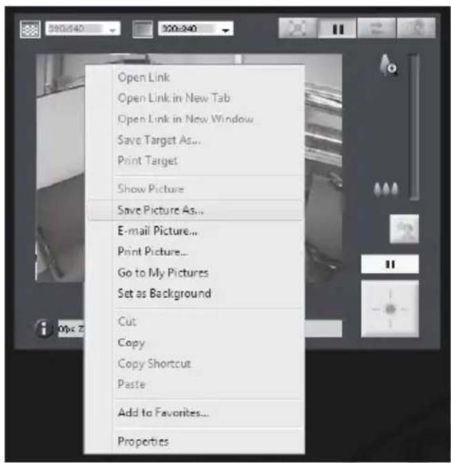
text_image
Open Link Open Link in New Tab Open Link in New Window Save Target As... Print Target Show Picture Save Picture As... E-mail Picture... Print Picture... Go to My Pictures Set as Background Cut Copy Copy Shortcut Paste Add to Favorites... Properties- Click the "Pause/Resume" button to pause video.
- Bring the cursor over the video screen and right-click the mouse to display the pop-up menu.
- Select [Save Picture As].
- Enter a file name and save the image.
* Although the sample screen is that of Admin Viewer, you can also save the image in VB Viewer using the same operation.

Tip
When the video is paused, functions others than Video Display Size, the Pause/Resume button, the Control for Admin button, and the Control for Admin items except the followings are grayed out.
- External Input Status Display - Motion Detection Status Display Function returns to normal after playback is resumed.
■ Reconnect
This function is used to connect to the camera again.
To reconnect the camera, click this button.

Tip
Once the camera is reconnected, audio reception will stop.
The control privileges will be abandoned and the video capture size and video display size will also return to the defaults.
■ Receiving Audio
You can receive audio through the microphone attached to the camera.
text_image
User interface buttons including double and double left indicators with a speaker iconClick this button to receive audio.

Tip
- To receive audio, set [Enable] for [Audio Transmission from the Camera] under [Audio Server] of [Server] on the setting page beforehand (→ P. 1-29).
● Audio cannot be received if you are using a proxy server.
Displaying Information
Viewer information, warning messages, etc., are shown.
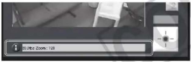
text_image
55.8% Zoom : 128■ Information Message
An information message is indicated by a blue icon.
An information message appears when a camera operation has been successful.
Help messages on various buttons, pull-down lists, etc., and zoom, frame rate and other information from the camera are shown.
■ Warning Message

A warning message is indicated by a yellow icon.
If an unsupported web browser is used or audio reception stops, a message will be displayed to alert the user.
■ Error Message

An error message is indicated by an orange icon.
An error message will be displayed if the viewer generates an error.

Tip
For details on the above messages, see "List of VB-C500 Viewer Messages" ( P. 5-17).
Performing Operations and Settings as the Administrator
The operations and settings that can only be performed in the Admin Viewer are explained.
Opening Control for Admin Panel
How to Operate
- Click "Obtain/release Camera Control" button to obtain the control privileges.
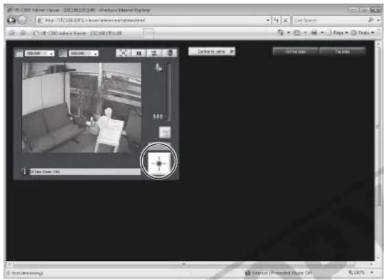
text_image
VIR-CERO Adyen Visual - 192.068.195.140 - Windows Internet Explorer http://192.068.195.140/Internet/Adyen/Adyen/Adyen/Adyen VIR-CERO Adyen Review - 192.068.195.140 Video Video Audio Audio Search Maps Tools Video Video Audio Audio Search Video Audio Audio Search Video Audio Audio Search Video Audio Audio Search Video Audio Audio Search Video Audio Audio Search Video Audio Audio Search Video Audio Audio Search Video Audio Audio Search Video Audio Audio Search Video Audio Audio Search Video Audio Audio Search Video Audio Audio Search Video Audio Audio Search Video Audio Audio Search Audio Audio Audio Search Video Audio Audio Search Video Audio Audio Search Video Audio Audio Search Video Audio Audio Search Video Audio Audio Search Video Audio Audio Search Video Audio Audio Search Video Audio Audio Search Video Audio Audio Search Video Audio Audio Search Video Audio Audio Search Video Audio Audio Search Video Audio Audio Search Video Radio Drive (192) Radio Drive (192) Radio Drive (192) Radio Drive (192) Radio Drive (192) Radio Drive (192) Radio Drive (192) Radio Drive (192) Radio Drive (192) Radio Drive (192) Radio Drive (192) Radio Drive (192) Radio Drive (192) Radio Drive (192) Radio Drive (192) Radio drive (192) Radio drive (192) Radio drive (192) Radio drive (192) Radio drive (192) Radio drive (192) Radio drive (192) Radio drive (192) Radio drive (192) Radio drive (192) Radio drive (192) Radio drive (192) Radio drive (192) Radio drive (192) Radio drive (300)- Click [Control for Admin].

- The Control for Admin panel appears.

text_image
VR-C80 Admin Viewer - 132.268.190.45 - Wireless Internet Explorer http://132.268.190.45/132.268.190.45/132.268.190.45/132.268.190.45/132.268.190.45/132.268.190.45/132.268.190.45/132.268.1 VR-C80 Admin Viewer - 132.168.190.45/132.268.190.45/132.268.190.45/132.268.190.45/132.268.190.45/132.268.190.45/132.268.190.45 VR-C80 Admin Viewer - 132.168.190.45/132.268.190.45/132.268.190.45/132.268.190.45/132.268.190.45/132.268.190 VR-C80 Admin Viewer - 132.168.190.45/132.268.190.45/132.268.190.45/132.268.190.45/132.268.190 VR-C80 Admin Viewer - 132.168.190.45/132.268.13 VR-C80 Admin Viewer - 132.168.190.45/132.268.13 VR-C80 Admin Viewer - 132.168.190.45/132.268.13 VR-C80 Admin Viewer - 132.168.190.45/132.268 VR-C80 Admin Viewer - 132.168.190.45/132.268 VR-C80 Admin Viewer - 132.168.190.45/132.268 VR-C80 Admin Viewer - 132.168.190.45/132.268 VR-C80 Admin View VR-C80 Admin View VR-C80 Admin View VR-C80 Admin View VR-C80 Admin View VR-C80 Admin View VR-C80 Admin View VR-C80 Admin View VR-C80 Admin View VR-C80 Admin View VR-C80 Admin View VR-C80 Admin View VR-C80 Admin View VR-C80 Admin View VR-C80 Admin View FRM Display Photo Display Auto Auto (Display) Auto (Display) Auto (Display) Auto (Display) Auto (Display) Auto (Display) Auto (Display) Auto (Display) Auto (Display) Auto (Display) Auto (Display) Auto (Display) Auto (Display) Auto (Display) Auto (Display) Auto (Display) Auto (Display) Auto (Display) Auto (Display) Auto (Display) Auto (Display) Auto (Display) Auto (Display) Auto (Display) Auto (Display) Auto (Display) Auto (Display) Auto (Display) Auto (Display) Auto (Display) Auto (Display) Auto (Display) Auto (Display) Auto (Display) Auto (Display) Auto (Display) Auto (Display) Auto (Display) Auto (Display) Auto (Display) Auto (Display) Auto (Display) Auto (Display) Auto (Display) Auto (Display) Auto (Display)* You can open Control for Admin without camera control privileges, but all items in the Control for Admin operation area except External Input Status Display and Motion Detection Status Display are grayed out.
Operating the External Device Output
You can operate the external device output and display the current output status using an icon.
The [ON]/[OFF] status can be switched by clicking this icon.

text_image
External Device Output Output 1 Output 2Example:
Top: Output OFF
Bottom: Output ON
Displaying the External Device Input Status
You can check the status of external device input and display it using an icon. When the external device receives a contact input signal, the input will turn ON and an applicable icon will appear.

text_image
External Device Input Input 1 Input 2Example:
Top: Input OFF
Bottom: Input ON
Displaying the Motion Detection Status
You can display the detection status of the motion detection function.

text_image
Motion Detection Area 1 Area 2 Area 3 Area 4Example:
Areas 1 to 3: Detection status OFF
Area 4: Detection status ON

Tip
Set the motion detection options beforehand using "Motion Detection Setting Tool" of VBAdmin Tools ( P. 2-7).
Controlling/Setting the Camera
Click the applicable camera control buttons to perform zoom operation and set the speed of each operation.

text_image
Zoom: Fast Slow(1) Zoom in/out buttons
You can zoom in to/out of the displayed image. Press and hold a button, and the camera will zoom continuously. Release the button, and the camera will stop.

Tip
Even when the [Zoom] speed setting is changed, the speed of zoom operation performed using the scroll bar will not change.
(2) [Zoom] speed
Select a desired operation speed from [Fast] and [Slow].
![CANON VB-C500D - [Zoom] speed - 1](/content/2026/06/1214332/images/f588b4e05537e8b3a51b7f6094f9b2caa8f588e3ce3a7158e03a9a3276c8e9e1.jpg)
Tip
Even when the [Zoom] speed setting is changed, the speed of zoom operation performed using the scroll bar will not change.
Setting the Exposure
You can set various options relating to exposure operation.
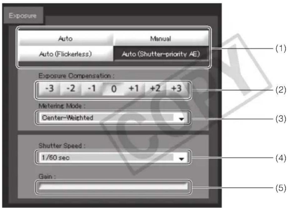
text_image
Exposure Auto Manual Auto (Flickerless) Auto (Shutter-priority AE) (1) (2) Exposure Compensation : -3 -2 -1 0 +1 +2 +3 Metering Mode : Center-Weighted (3) Shutter Speed : 1/60 sec (4) Gain : (5)(1) Exposure Mode
Select [Auto], [Manual], [Auto (Flickerless)] or [Auto (Shutter-priority)].
If [Auto] was selected for [Day/Night] under [Camera] on the setting page ( P. 1-17), select [Auto], [Auto (Flickerless)] or [Auto (Shutter-priority)].
For explanation on each item set in the exposure mode, see the setting page ( P. 1-15).
(2) Exposure Compensation
When [Auto], [Auto (Flickerless)] or [Auto (Shutter-priority)] is selected as the exposure mode, a desired exposure compensation value can be selected from seven levels (-3 to +3) using an applicable button.
To darken the image, select a negative value. To brighten the image, select a positive value.
(3) Metering Mode
When [Auto], [Auto (Flickerless)] or [Auto (Shutter-priority)] is selected as the exposure mode, select a desired metering mode from [Center-Weighted], [Average] and [Spot].
[Center-Weighted]
The entire screen is metered by focusing on the center of the screen.
Even when slightly darker/brighter areas are present on the periphery of the screen, an appropriate exposure can be achieved for the subject near the center.
Use this mode if the subject is positioned near the center of the screen.
[Average]
The entire screen is metered by averaging.
A stable exposure can be achieved even in a capture environment where there are notable brightness differences within the screen.
Use this mode to stabilize the exposure in locations where vehicles or people are moving.
[Spot]
The center of the screen is metered.
An appropriate exposure can be achieved for the subject at the center of the screen regardless of the brightness/darkness on the periphery of the screen.
Use this mode if you want to adjust the exposure to the center of the screen because the subject is receiving a spotlight or backlight, etc.
(4) [Shutter Speed]
When [Manual] or [Auto (Shutter-priority)] is selected as the exposure mode, select a desired shutter speed. If [Manual] is selected, set the shutter speed from the pull-down menu in a range of [1/1 sec] to [1/8000] . If [Auto (Shutter-priority)] is selected, set the shutter speed from the pull-down menu in a range of [1/8] to [1/8000] .
(5) [Gain]
When [Manual] is selected as the exposure mode, set a desired value of gain.
Moving the slider to the left decreases the gain (sensitivity to brightness) and darkens the image. Moving the slider to the right increases the gain and brightens the image.
![CANON VB-C500D - [Gain] - 1](/content/2026/06/1214332/images/fba0c1181684798161323d628cb63f71cf902d28a58160c46acbdce11a0c8a96.jpg)
Note
If the subject is a traffic signal, electronic scoreboard, etc., the captured image may flicker. In this case, try changing the exposure mode to [Auto (Shutter-priority)] and then select a shutter speed lower than 1/100, to see if the situation improves.
Setting the White Balance
Select a desired white balance setting from [Auto], [Light Source] and [Lock].
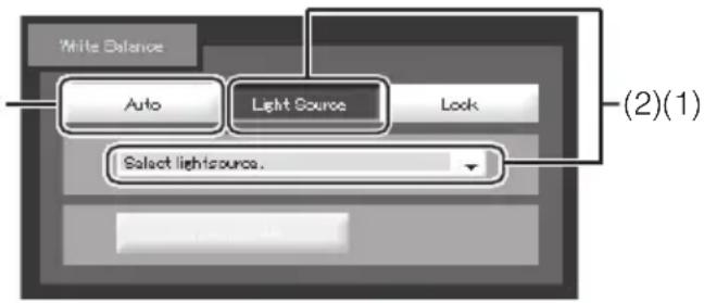
text_image
White Balance Auto Light Source Look (2)(1) Select lightsource.(1) [Auto]
The white balance is adjusted automatically.
(2) [Light Source]
Select the light source from the pull-down menu below according to the condition in which the camera is used.
| [Daylight Fluorescent] | :Select this option to capture video under daylight fluorescent lighting. |
| [White Fluorescent] | :Select this option to capture video under neutral white or cool white fluorescent lighting. |
| [Warm Fluorescent] | :Select this option to capture video under warm color fluorescent lighting. |
| [Mercury Lamp] | :Select this option to capture video under mercury lamps. |
| [Sodium Lamp] | :Select this option to capture video under orange sodium lamps. |
| [Halogen Lamp] | :Select this option to capture video under halogen bulbs or incandescent bulbs. |
![CANON VB-C500D - [Light Source] - 1](/content/2026/06/1214332/images/67693458c266aa025c3ba3886fde929eac74d635f4d005445eec64b75c072b85.jpg)
text_image
White Balance Auto Light Source Lock Select lightsource One-shot WB (3)(3) [Lock]
The white balance is fixed to that of the video currently received.
To forcibly fix the white balance according to the light source, use [One-shot WB].
Example of setting method:
Irradiate a white subject (white paper, etc.) using the light source and capture the subject over the entire screen. In this condition, select [One-shot WB].
![CANON VB-C500D - [Lock] - 1](/content/2026/06/1214332/images/4ab9802d8222ec6186311307ec21740fa788365804cea5b7e6f7cb7ec74ddccb.jpg)
Note
- Since the light source selection options are based on representative characteristics, proper colors may not be achieved depending on the applicable light source. In this case, use the [One-shot WB] function.
- If the image looks greenish under mercury lamps in the [Auto] mode, select the [Mercury Lamp] mode under Light Source. If the image is still not shown in appropriate colors under mercury lamps when the [Mercury Lamp] mode is selected under Light Source, use the [Auto] mode.
- Notes on capturing video continuously day and night If a subject that seldom changes is captured in a location where the light source changes gradually, such as when capturing such subject continuously day and night, the image may not be shown in appropriate colors.
- When the subject has only one color or when sodium lamps, mercury lamps and certain other fluorescent lightings are used, camera colors may not be adjusted automatically.
Setting the Smart Shade Control
Smart Shade Control is a function that, unlike the Backlight Compensation, brightens only dark areas while keeping bright areas intact.

text_image
Smart State Control On Off 1 2 3 4 5 6 7 (1) (2)(1) Smart Shade Control
Set [OFF] or [ON].
(2) Adjusting the Smart Shade Control
When [On] is selected for Smart Shade Control, set one of seven control levels from [1] (weak) to [7] (strong).
Example) If the background is bright and the subject is hard to see, this function brightens dark areas to make the subject clearer. Compared to Backlight Compensation, Smart Shade Control can reduce blown-out of bright areas.
natural_image
Black-and-white photo of a woman walking past a window with windows and outdoor structures (no visible text or symbols)
natural_image
Black-and-white photo of a woman carrying a box standing near a window with windows and outdoor landscaping (no visible text or symbols)
natural_image
Silhouette of a woman walking past a window with large windows (no text or symbols visible)OFF Smart Shade Control Backlight Compensation

Tip
- When [On] is selected for Smart Shade Control, the video file size increases.
- When [On] is selected for Smart Shade Control, screen noises may increase. If noises are noticeable, lower the control level.
Setting the Night Mode
Switch between [Day Mode] and [Night Mode].

text_image
Night Mode Day Mode Night Mode
Tip
The Night Mode cannot be used if [Auto] is set for Day/Night under [Camera] on the setting page ( P. 1-16).
[Day Mode]
Color image can be viewed in the normal mode.
[Night Mode]
Images are shown in black & white.
4
Creating Web Pages for Video Distribution
This chapter explains how to distribute image using the VB-C500VD/VB-C500D.
You can distribute image in various ways, such as displaying video or still images or showing multiple images on a Web page.
You must create a dedicated Web page to distribute information from the camera you have installed. "VB-C500 Viewer" can be used as the camera's viewer, where you can set detailed parameters.

flowchart
graph TD
    A["HTTP (WWW) server"] --> B["Internet"]
    B --> C["Dedicated Web server"]
    B --> D["Viewer PC"]
    B --> E["VB-C500VD/VB-C500D"]
    B --> F["(1) Access the Web page"]
    B --> G["(2) Notify the IP address information"]
    B --> H["(3) Request t"]
    B --> I["(4) Distribute image"]
If a link corresponding to the image request is selected in (1), the Web server will send a file containing the IP address information of the camera from the server in (2). If VB Viewer is used, the camera will deliver video to the viewer PC upon the request in (3).
■ Sample Web Page for Video Distribution (Built in the Camera)
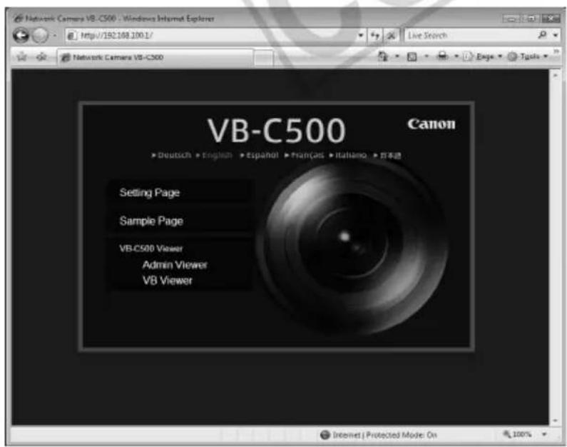
text_image
Network Camera VB-C500 - Windows Internet Explorer http://192.188.1001/ Live Search Network Camera VB-C500 VB-C500 Canon ► Deutsch ► English ► Spanish ► Français ► Italiano ► 日本通 Setting Page Sample Page VB.C500 Viewer Admin Viewer VB Viewer Internet | Protected Mode On 100%The above page is built in the camera. It can be accessed from the following URL:
http://192.168.100.1/
* The underlined portion is an example of IP address. In reality, the customer must enter the IP address set for the camera ( P. 1-8).

Note
The VB-C500VD/VB-C500D has a built-in Web server. Write desired content for the Web page for video distribution in the flash memory in the camera beforehand, and you can publish the Web page and distribute image over the Web using the camera alone. For information on how to save Web page data, see "How to Create a Web Page Using VB Viewer" (→ P. 4-6).
Please make sure that the web server and the camera's IP address or global address are on the same subnet, when using a dedicated web server.

Tip
You can utilize the language setting function of the browser to create a multi-language Web page.
For example, set the top page for Japanese users as index-ja.html and English page for overseas users as index.html, and separate the URL with slashes, such as http://192.168.100.1/sample/. This way, the server will send appropriate files according to the browser's language setting for the accessed page. For details on the language setting function, see the browser's Help.
* The underlined portion is an example of IP address. In reality, the customer must enter the IP address set for the camera ( P. 1-8).
This camera stores sample pages for video distribution. You can view the sample pages by following the procedure below. Use these samples as a reference when creating a Web page.
How to View
- Launch the Web browser and enter the following URI:
http://192.168.100.1/sample/
* The underlined portion is an example of IP address. In reality, the customer must enter the IP address set for the camera ( P. 1-8).
* You can also select "Sample Page" on the top page to view the sample pages ( P. xi).
- When the following pages are displayed, click the sample page you want to view.
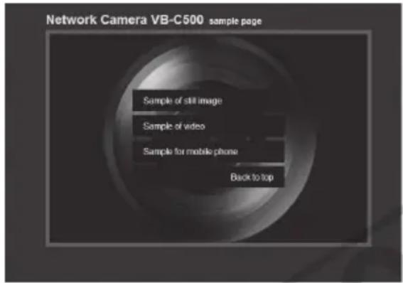
text_image
Network Camera VB-C500 sample page Sample of still image Sample of video Sample for mobile phone Back to top■ Example of sample page
Still image sample
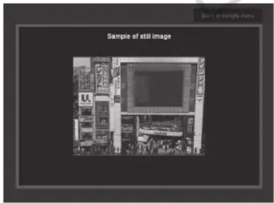
text_image
Sample of still image Back to simple menThis is a sample page for acquiring still images from the camera and displaying the acquired images.
Movie sample

text_image
Back to sample menu Sample of videoThis is a sample page for displaying live video.
Sample for mobile phone
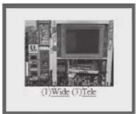
natural_image
Interior view of a computer room with monitor and keyboard (no visible text or symbols)This is a sample page for displaying still images with camera operation function for mobile phones. (These images can also be displayed in normal Web browsers for PCs.)
How to provide image using VB Viewer is explained, together with application examples.
How to Create a Web Page Using VB Viewer
You can display VB Viewer by incorporating it into your Web page.
<iframe src="http://192.168.100.1/viewer/live/en/live.html" scrolling="no" width=490 height=500> </iframe>
* The underlined portion is an example of IP address. In reality, the customer must enter the IP address set for the camera ( P. 1-8).
If you are saving the Web page to the flash memory in the camera, you can also omit the IP address, as follows:
